Method of detecting defects on face automatically
- Summary
- Abstract
- Description
- Claims
- Application Information
AI Technical Summary
Benefits of technology
Problems solved by technology
Method used
Image
Examples
first embodiment
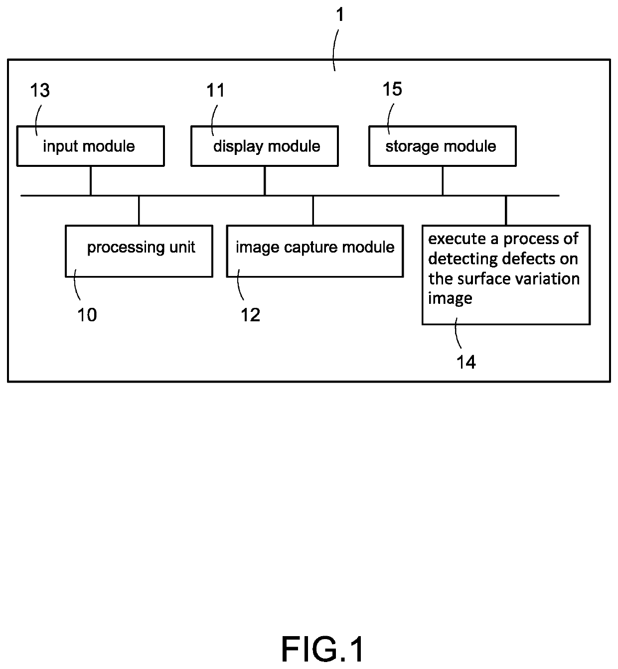
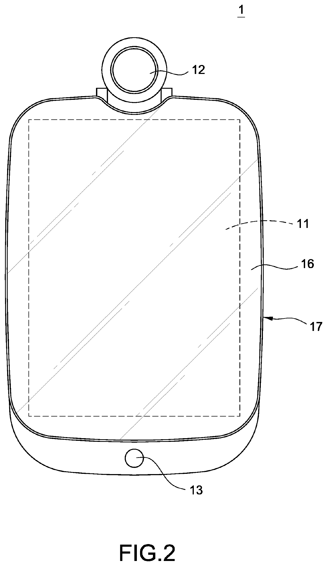
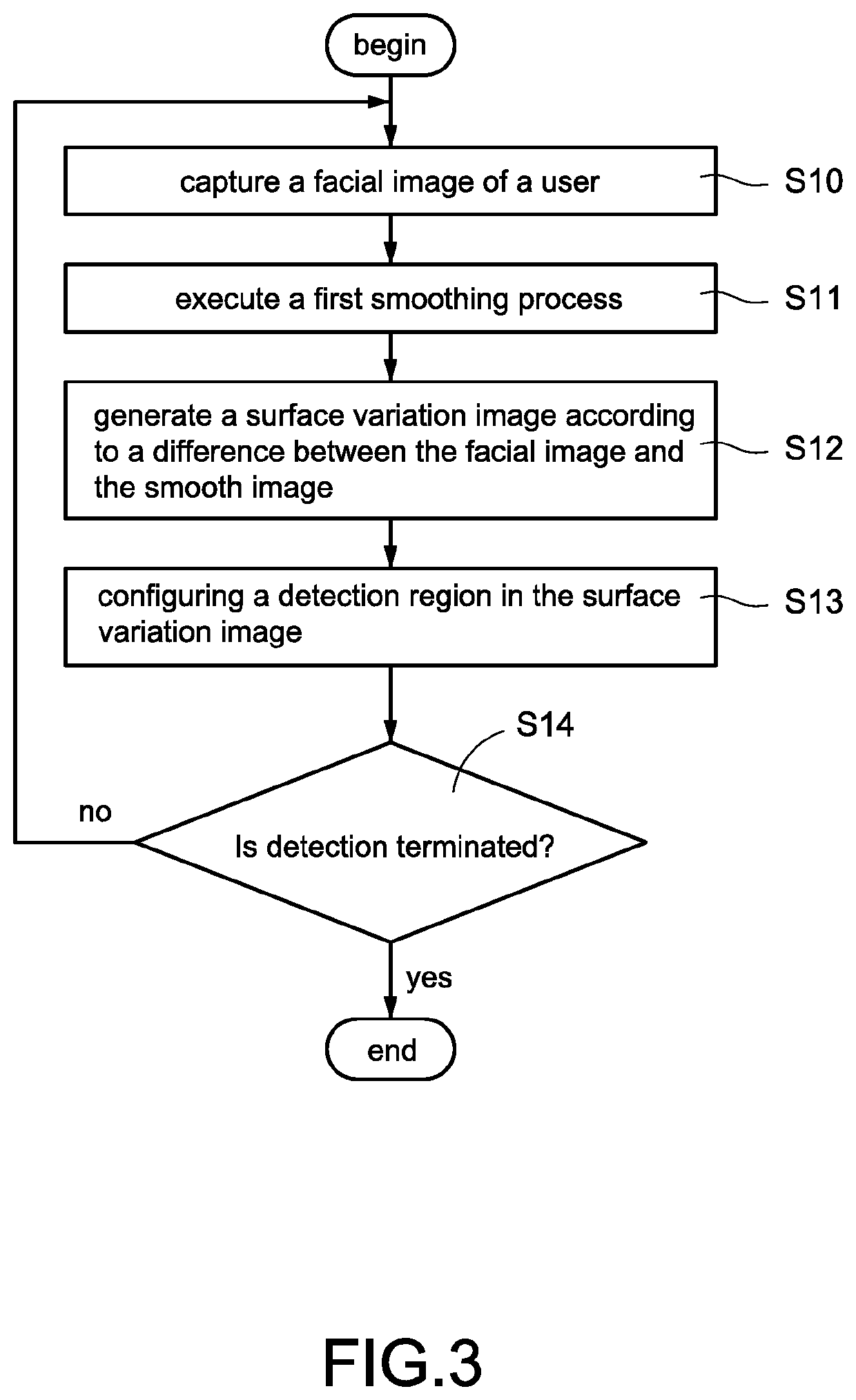
[0038]Please refer to FIG. 3 simultaneously, which is a flowchart of a method of detecting defects on face automatically according to the present disclosed example. The method of detecting defects on face automatically of each embodiment of the present disclosed example may be implemented by the smart mirror apparatus shown in FIG. 1 and FIG. 2.
[0039]The method of detecting defects on face automatically of this embodiment mainly comprises following steps.
[0040]Step S10: the processing unit 10 controls the image capture module 12 to capture the facial image of the user.
[0041]One of the exemplary embodiments, the processing unit 10 captures the user's facial image when detection of the user is located in front of the smart mirror apparatus 1. More specifically, the processing unit 10 is configured to control the image capture module 12 to capture toward the front side of the mirror glass 16 continuously for continuously obtaining the front mirror images with a wider field of view and ...
second embodiment
[0058]Please refer to FIG. 3, FIG. 4, FIG. 9 and FIG. 10 simultaneously, FIG. 4 is a flowchart of applying detection result according to the present disclosed example, FIG. 9 is a schematic view of a function of marking defects according to one of the embodiments of the present disclosed example, and FIG. 10 is a schematic view of a function of concealing defects according to one of the embodiments of the present disclosed example.
[0059]This embodiment is a further application of the position of each defect obtained by the method of detecting defects on face automatically of the FIG. 3. In this embodiment, the display module 11 of the smart mirror apparatus 1 is arranged beside the mirror glass 16, and the screen pictures (such as the electronic mirror image) of the display module 11 appear on the mirror glass 16 by transmission.
[0060]More specifically, in this embodiment, the smart mirror apparatus 1 may implement a function of marking defects (implemented in the mode of marking de...
third embodiment
[0076]Please refer to FIG. 3-5, FIG. 11, and FIG. 12 simultaneously, FIGS is a flowchart of a process of concealing defects according to the present disclosed example, FIG. 11 is a first processing schematic view of a function of concealing defects according to one of the embodiments of the present disclosed example, and FIG. 12 is a second processing schematic view of a function of concealing defects according to one of the embodiments of the present disclosed example.
[0077]This embodiment provides a scheme of the process of concealing defects of the step S23 shown in FIG. 4, the scheme comprises the following steps.
[0078]Step S30: the processing unit 10 retrieves above-mentioned surface variation image, and executes a dilation process on an image of each defect in the surface variation image for expanding an image area of each defect in the surface variation image.
[0079]One of the exemplary embodiments, as shown in FIG. 11, a detection region is configured in the surface variation...
PUM
 Abstract
Description
Claims
Application Information
 - R&D
- Intellectual Property
- Life Sciences
- Materials
- Tech Scout
- Unparalleled Data Quality
- Higher Quality Content
- 60% Fewer Hallucinations
Browse by: Latest US Patents, China's latest patents, Technical Efficacy Thesaurus, Application Domain, Technology Topic, Popular Technical Reports.
© 2025 PatSnap. All rights reserved.Legal|Privacy policy|Modern Slavery Act Transparency Statement|Sitemap|About US| Contact US: help@patsnap.com


