Method for inspecting defect of hollow fiber porous membrane, defect inspection equipment and production method

a inspection equipment technology, applied in the field of hollow fiber porous membrane inspection methods, can solve the problems of inability to adapt and reduce yield, and achieve the effect of accurately measuring an internal defect of the target hollow fiber membrane, increasing the absolute quantity of light intensity, and preventing heat generation

Inactive Publication Date: 2011-05-10
ASAHI KASEI CHEM CORP
View PDF12 Cites 7 Cited by
  • Summary
  • Abstract
  • Description
  • Claims
  • Application Information

AI Technical Summary

Benefits of technology

[0015]The irradiation chamber includes; the irradiation means for emitting light from the outside of a hollow fiber porous membrane; and the light shielding means for preventing irradiation light from directly leaking to the outside of the irradiation chamber. The irradiation means may be of any type as long as it can irradiate the hollow fiber porous membrane with light, however, an irradiation means using white light is preferable because it can increase the absolute quantity of light intensity.
[0041]For the S / N ratio, considering variations in the normal light intensity and noise, the threshold value for detecting a defect is desirably set equal to or greater than 1.5 times the normal light intensity. Therefore, the S / N ratio equal to or greater then 1.5 would make it possible to detect a defect accurately. Even if the SN ratio falls below 1.5, the S / N ratio equal to or greater than 1.2 would enable the measurement by improving the accuracy in shielding the outside light. In Examples 1 to 4, the SN ratio is equal to or greater then 1.5 and a defect portion could be detected without being affected by variations in the normal light intensity. The brightness profile at a defective position of Example 3 is shown in FIG. 3(a). In FIG. 3(a), reference numeral 8 indicates the brightness profile of an internal defect and reference numeral 9 indicates the brightness profile of a normal portion.

Problems solved by technology

Conventionally, in the internal-defect inspection of a hollow fiber porous membrane, a visual inspection cannot be performed because the shape of the hollow fiber porous membrane is cylindrical and opaque, and therefore, a destructive inspection method has been used, wherein an internal pressure is applied to destruct the hollow fiber porous membrane.
Since the hollow portion is usually pressurized after a hollow fiber membrane module is formed, the inspection is performed in the units of module products and therefore the loss due to a defect increases, causing a decrease in the yield.
This technique can shield the neither scattered light nor transmitted light at an edge portion of a cylindrical hollow fiber porous membrane and therefore cannot be adapted for the inspection of an internal defect causing a pinhole of a target hollow fiber porous membrane.

Method used


Image

  • Method for inspecting defect of hollow fiber porous membrane, defect inspection equipment and production method
  • Method for inspecting defect of hollow fiber porous membrane, defect inspection equipment and production method
  • Method for inspecting defect of hollow fiber porous membrane, defect inspection equipment and production method

Examples


example 1

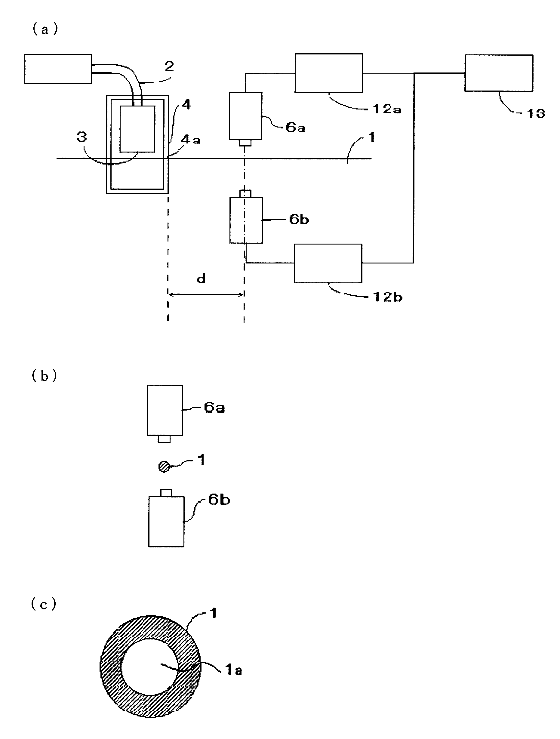
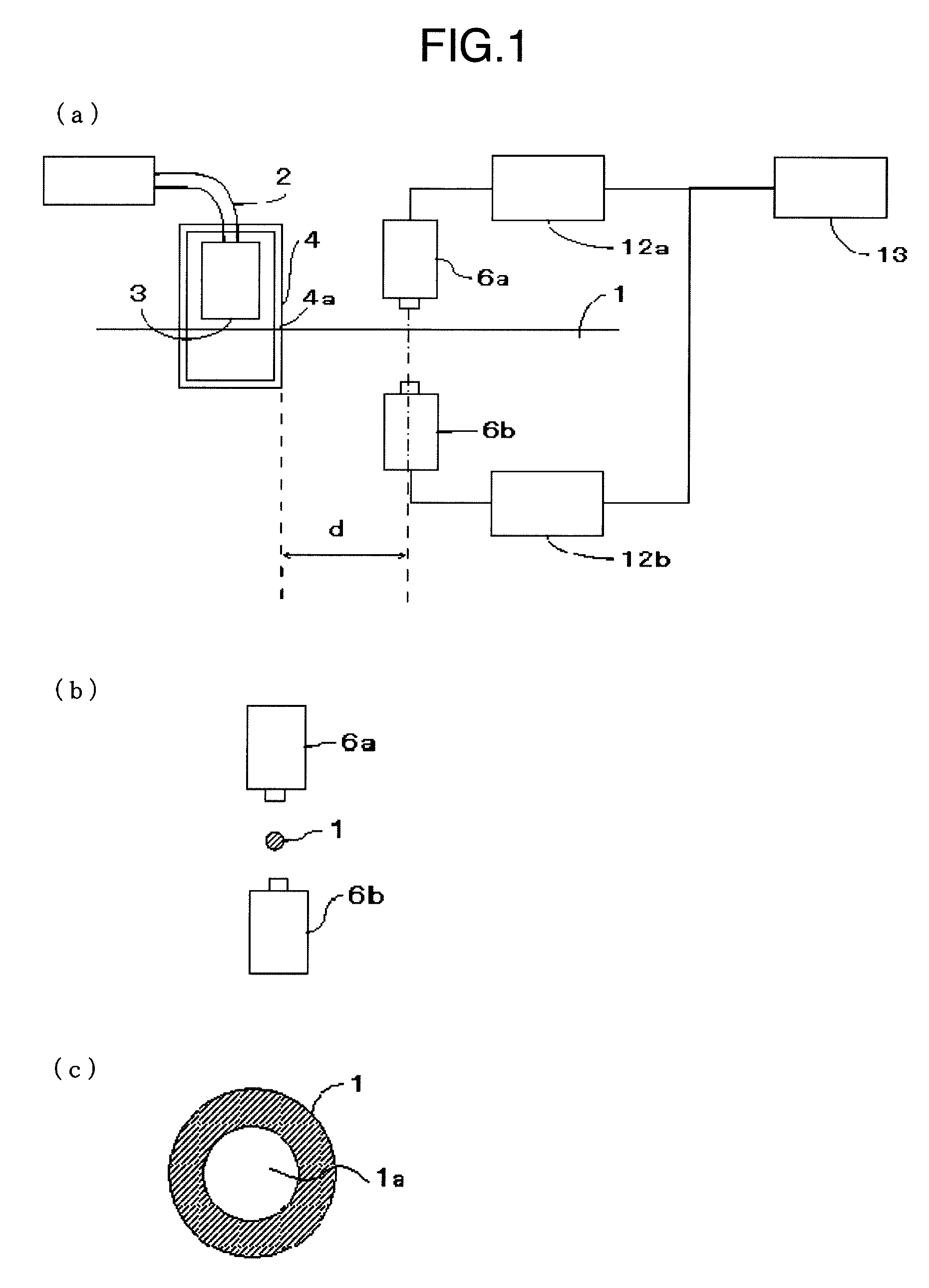
[0033]A spinning dope containing polysulfone (Udel P-3500 manufactured by SOLVAY) as the raw material and N-methylpyrrolidone as a solvent was injected, together with water of an internal liquid, in the form of a hollow fiber in the air and was then solidified in a coagulation bath, thereby producing a hollow fiber porous membrane using 16 spinning spindles at a line velocity of 20 m / min. Prior to being wound up after taken out of the coagulation bath and through a washing process, the hollow fiber porous membrane 1 (with outer diameter of 1.4 mm and inner diameter of 0.8 mm) was introduced into the irradiation chamber 4 (to serve as the through-hole 4a with a hole size of 1.8 mm opened at 1 mm intervals when the upper lid is closed) manufactured by SUS, the irradiation chamber including therein the line-type optical fiber illuminating device 2 (metal halide illuminating device: MLDS250 (250 W) manufactured by Iwasaki Electric Co., Ltd.) and a line-type light guide: GF8-1L1500 R-S10...

examples 2 to 6

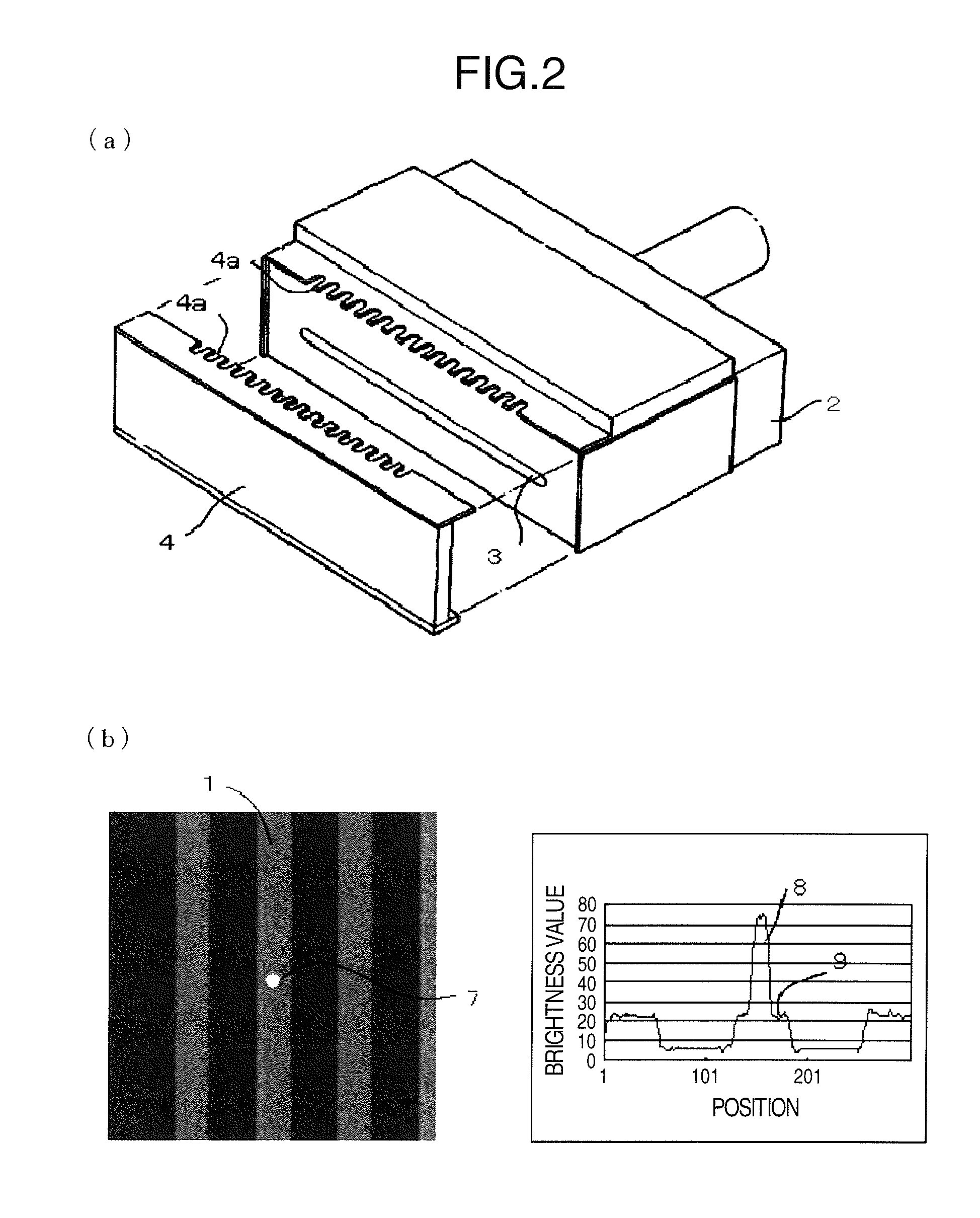
[0035]The defect targeted at in the method of the present invention is a non-through defect (a cavity enclosed in the hollow fiber porous membrane) that will be destroyed by a practical operating pressure. However, it is difficult to experimentally form a non-through defect and therefore a model experiment was conducted by artificially opening a pinhole in the hollow fiber porous membrane which was spun in Example 1. The same defect detection device as that of Example 1 was used. The detection condition of each example is shown in Table 1.

[0036]A hollow fiber membrane having a pinhole opened therein was introduced into the defect detection device and was then imaged with the imaging distance d of the line-sensor camera 6a in a range of 0.2 to 5.6 mm, and then the output values of the line-sensor camera were digitized into 0 to 511 levels, which were then image-processed to obtain a brightness profile. A ratio of the output values of an un-through pinhole and an artificially opened t...


PUM

PropertyMeasurementUnit
thicknessaaaaaaaaaa
diameteraaaaaaaaaa
thicknessaaaaaaaaaa

Abstract

A method for inspecting a defect of a hollow fiber porous membrane having substantially uniform, continuous inner hollow portions comprises steps for introducing a part of the hollow fiber porous membrane into an irradiation chamber, for irradiating the hollow fiber porous membrane with light from the outside in the irradiation chamber, and for detecting light exiting the hollow fiber porous membrane on the outside of the irradiation chamber.

Description

TECHNICAL FIELD[0001]The present invention relates to a method for inspecting a defect of a hollow fiber porous membrane, defect inspection equipment, and a production method.BACKGROUND ART[0002]Conventionally, in the internal-defect inspection of a hollow fiber porous membrane, a visual inspection cannot be performed because the shape of the hollow fiber porous membrane is cylindrical and opaque, and therefore, a destructive inspection method has been used, wherein an internal pressure is applied to destruct the hollow fiber porous membrane. The destructive inspection can be performed by pressurizing a hollow portion from both ends of a continuous single fiber. Since the hollow portion is usually pressurized after a hollow fiber membrane module is formed, the inspection is performed in the units of module products and therefore the loss due to a defect increases, causing a decrease in the yield.[0003]On the other hand, Patent Document 1 has proposed an on-line inspection method of ...

Claims


Application Information

Patent Timeline
Patent Type & Authority Patents(United States)
IPC IPC(8): G01N21/00
CPCB01D63/02B01D65/102B01D69/08G01N21/8914G01N21/894G01N21/952G01N21/8901G01N2021/8908G01B11/30G01N21/89G01N33/36
Inventor IKEDA, MAKOTOUCHIYAMA, RYUHEINAGASAWA, OSAMU
Owner ASAHI KASEI CHEM CORP
Why Eureka
Try Eureka