
Improved type a 2 /o biofilm synchronous decarbonization and nitrogen phosphorus removal reactor and its operation method

An operation method and improved technology, which is applied in the field of improved A2/O biofilm synchronous decarbonization and nitrogen and phosphorus removal reactor, can solve the problems that the function of the reaction zone cannot be fully exerted, the activity of bacteria is inhibited, and the sludge age is contradictory. , to achieve the effect of solving carbon source competition and efficient degradation

Active Publication Date: 2016-08-24
苏州科建环保科技有限公司
View PDF6 Cites 0 Cited by
  • Summary
  • Abstract
  • Description
  • Claims
  • Application Information

AI Technical Summary

Problems solved by technology

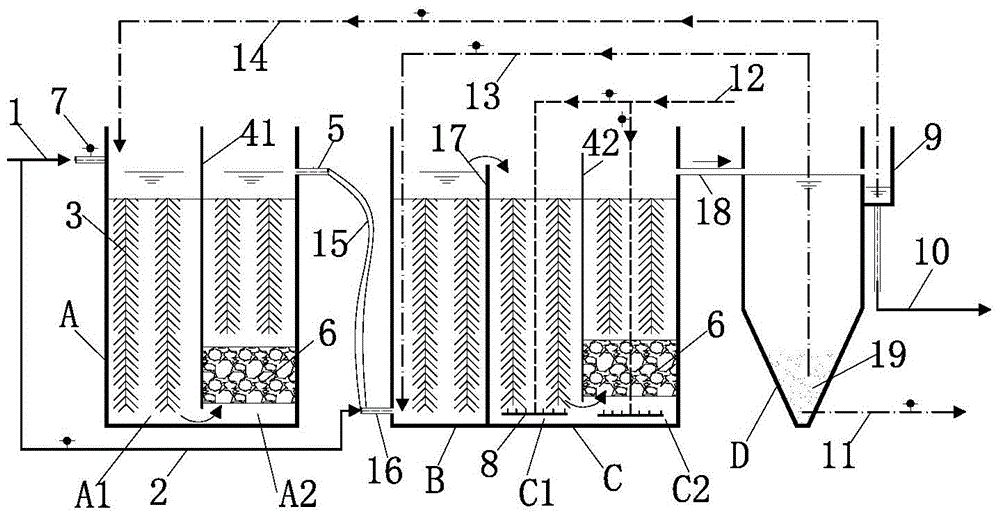
[0019] The object of the invention is to provide improved A 2 / O Biofilm Synchronous Decarbonization and Nitrogen and Phosphorus Reactor, Overcoming the Existing Conventional A 2 Defects in the / O process, to solve the problem of sludge age contradiction, the competition between nitrifying bacteria and denitrifying bacteria and other bacteria for substrate carbon sources, the problem that the functions of each reaction zone cannot be fully exerted due to the mixing of bacteria, mixed bacteria Continuous circulation in each reaction zone leads to the problem of inhibiting the activity of bacteria

Method used


Image

  • Improved type a  <sup>2</sup> /o biofilm synchronous decarbonization and nitrogen phosphorus removal reactor and its operation method
  • Improved type a  <sup>2</sup> /o biofilm synchronous decarbonization and nitrogen phosphorus removal reactor and its operation method
  • Improved type a  <sup>2</sup> /o biofilm synchronous decarbonization and nitrogen phosphorus removal reactor and its operation method

Examples


Embodiment 1

[0070] Embodiment 1: the treatment of conventional domestic sewage

[0071] see image 3 , The anoxic zone, the anaerobic zone, the aerobic zone and the sedimentation zone all adopt a cuboid structure, and the sedimentation zone adopts an advection sedimentation tank. The four pools use the same wall to save concrete materials. Raw water I first enters the anoxic zone, then enters the anaerobic zone and the subsequent aerobic zone, and finally exits from the sedimentation zone. The anoxic zone is divided into the first anoxic zone and the second anoxic zone by a partition, the first anoxic zone is filled with combined filler, and the volume of filler added is 70% of the total volume of the first anoxic zone; the second anoxic zone Add combined filler to the upper part of the zone, and add spherical suspended filler filled with volcanic rock particles to the lower part. The volume of the combined filler is 40% of the total volume of the second anoxic zone, and the volume of t...

Embodiment 2

[0075] Example 2: Treatment of low-carbon source domestic sewage

[0076] see Figure 4 , The connection mode and the operation process between each reaction zone of the reactor are the same as Example 1.

[0077] The control parameters are: the percentage of the water volume of the raw water I to the total water volume is 50%, and the percentage of the water volume of the raw water II to the total water volume is 50%. Nitrification liquid reflux ratio R=200%, sludge reflux ratio R=75%, dissolved oxygen DO is controlled at 0.3mg / L in anoxic zone, DO in anaerobic zone is controlled at 0.17mg / L, dissolved oxygen DO in aerobic zone Controlled at 1.8mg / L, dissolved oxygen DO in the refluxed nitrification solution was controlled at 0.6mg / L. The hydraulic retention time of sewage in the anoxic zone A is HRT=2.2h, the hydraulic retention time in the anaerobic zone B is HRT=8h, the hydraulic retention time in the aerobic zone C is HRT=12h, and the hydraulic retention time in the sed...

Embodiment 3

[0079] Embodiment 3: the treatment of textile printing and dyeing wastewater

[0080] see Figure 5 , Printing and dyeing wastewater first uses a lifting pump to lift the wastewater from the regulating tank to the coagulation tank. After adding chemicals to the coagulation tank, it enters the sedimentation tank for mud-water separation to remove part of the organic matter and suspended matter, while reducing the chroma of the raw water. The pretreated wastewater relies on gravity flow, enters the anoxic zone and anaerobic zone respectively according to the preset ratio of raw water I and raw water II, and then enters the subsequent aerobic zone in turn. After the biochemical reaction, the effluent enters the subsequent sedimentation area for mud-water separation, the sludge flows back to the anaerobic area, the nitrification solution flows back to the anoxic area from the effluent channel of the sedimentation area, and the remaining sludge is discharged for treatment. The con...


PUM

PropertyMeasurementUnit
particle diameteraaaaaaaaaa
porosityaaaaaaaaaa

Abstract

The invention discloses an improved A2 / O biological membrane reactor capable of synchronously removing carbon, nitrogen and phosphorus and an operation method thereof. The reactor comprises an anoxic area, an anaerobic area, an aerobic area and a precipitation area which are communicated with one another in sequence, wherein the raw water is divided into two raw water paths I and II which enter the anoxic area and the anaerobic area respectively; part of water discharged from the upper part of the precipitation area returns to the anoxic area; the sludge at the bottom of the precipitation area returns to the bottom of the anaerobic area; the anoxic area is filled with film formation fillers and spherical suspension fillers; the anaerobic area is filled with the film formation fillers; the aerobic area is filled with the film formation fillers and the spherical suspension fillers; the clear water at the upper part of the precipitation area flows through the reactor and is finally discharged by a water outlet pipe; the sludge at the bottom of the precipitation area is discharged by a sludge discharging pipe. By virtue of the reactor and the operation method thereof, the problems of sludge age contradiction, competition of different strains on substrate carbon source, the mixture of the strains, suppression on the activity of the strains and the like in the conventional A2 / O process can be effectively solved; the organic matters and nitrogen and phosphorus in the sewage can be synchronously and efficiently removed.

Description

technical field [0001] The invention relates to the technical field of environmental protection equipment, in particular to the improved A 2 / O biofilm synchronous decarbonization reactor for nitrogen and phosphorus removal and its operation method. Background technique [0002] With my country's increasingly stringent requirements for nitrogen and phosphorus removal and the generalization of low-carbon sources of sewage, most sewage treatment plants are faced with the problem that the nitrogen and phosphorus in the effluent cannot meet the standards and have to be upgraded. Although there are many technologies for denitrification and dephosphorization of sewage, the main role is still conventional A 2 / O process (including traditional A 2 / O process and inversion A 2 / O process), the world passes the conventional A 2 / O process to complete the denitrification and dephosphorization of sewage accounted for more than 80%. In my country's biological nitrogen and phosphorus...

Claims


Application Information

Patent Timeline
Patent Type & Authority Patents(China)
IPC IPC(8): C02F3/30
Inventor 郭永福
Owner 苏州科建环保科技有限公司
Learn More