Liquid cooled thermosiphon with flexible partition

a heat exchanger and liquid cooling technology, applied in the direction of lighting and heating apparatus, semiconductor/solid-state device details, laminated elements, etc., can solve the problem of relatively low air heat capacity and achieve the effect of enhancing the cooling capacity of tcu

Inactive Publication Date: 2006-07-27
DELPHI TECH INC
View PDF22 Cites 64 Cited by
  • Summary
  • Abstract
  • Description
  • Claims
  • Application Information

AI Technical Summary

Benefits of technology

[0014] The heat transfer rate of the two-phase secondary fluid is inherently higher than that of the single-phase working fluid. Therefore, besides enhancing the cooling capacity of the TCU, the invention solves the problem of corrosi...

Problems solved by technology

However, these electronic devices are increasingly being miniaturized and designed to achieve incre...

Method used


Image

  • Liquid cooled thermosiphon with flexible partition
  • Liquid cooled thermosiphon with flexible partition
  • Liquid cooled thermosiphon with flexible partition

Examples


Embodiment Construction

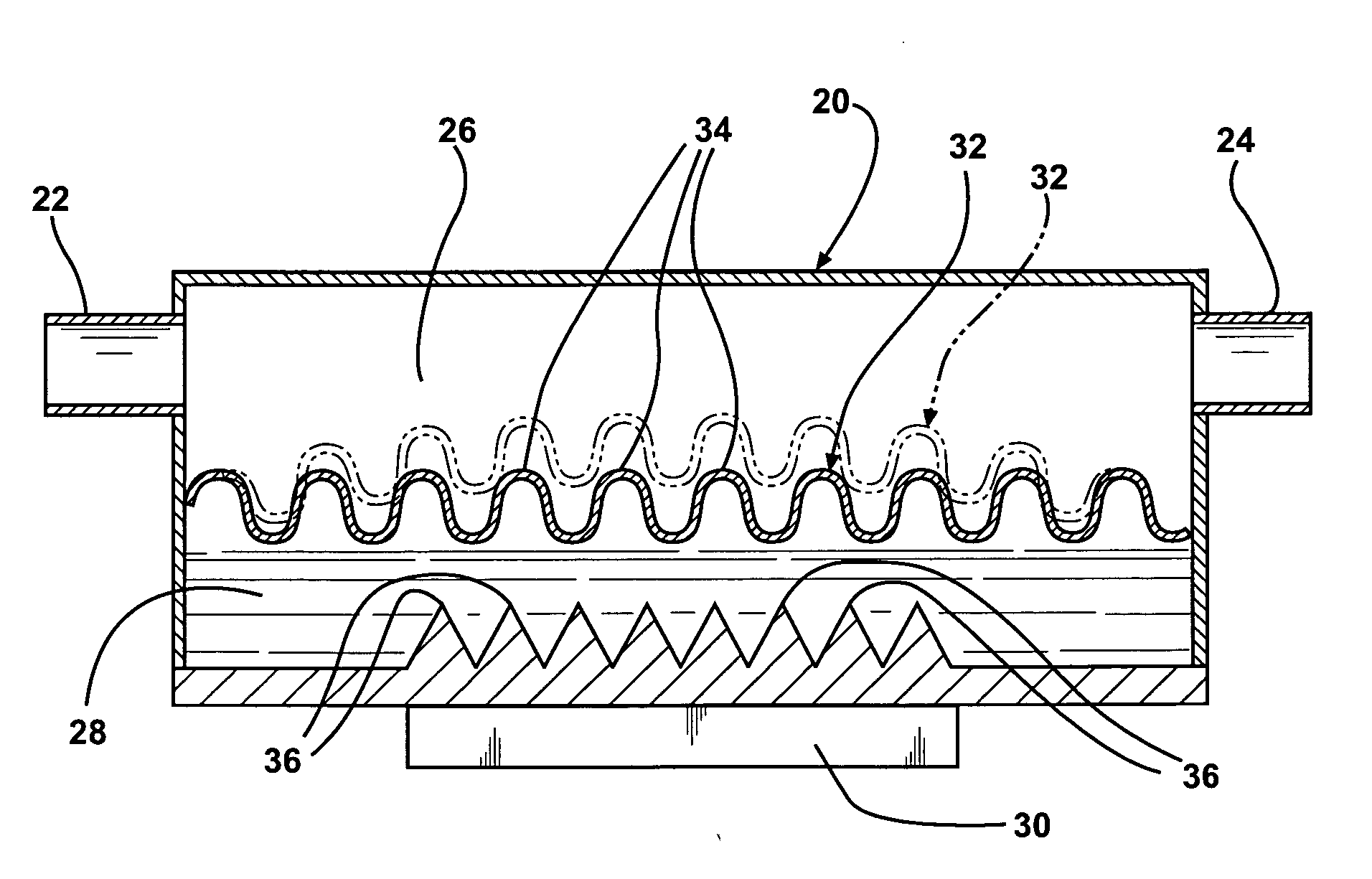
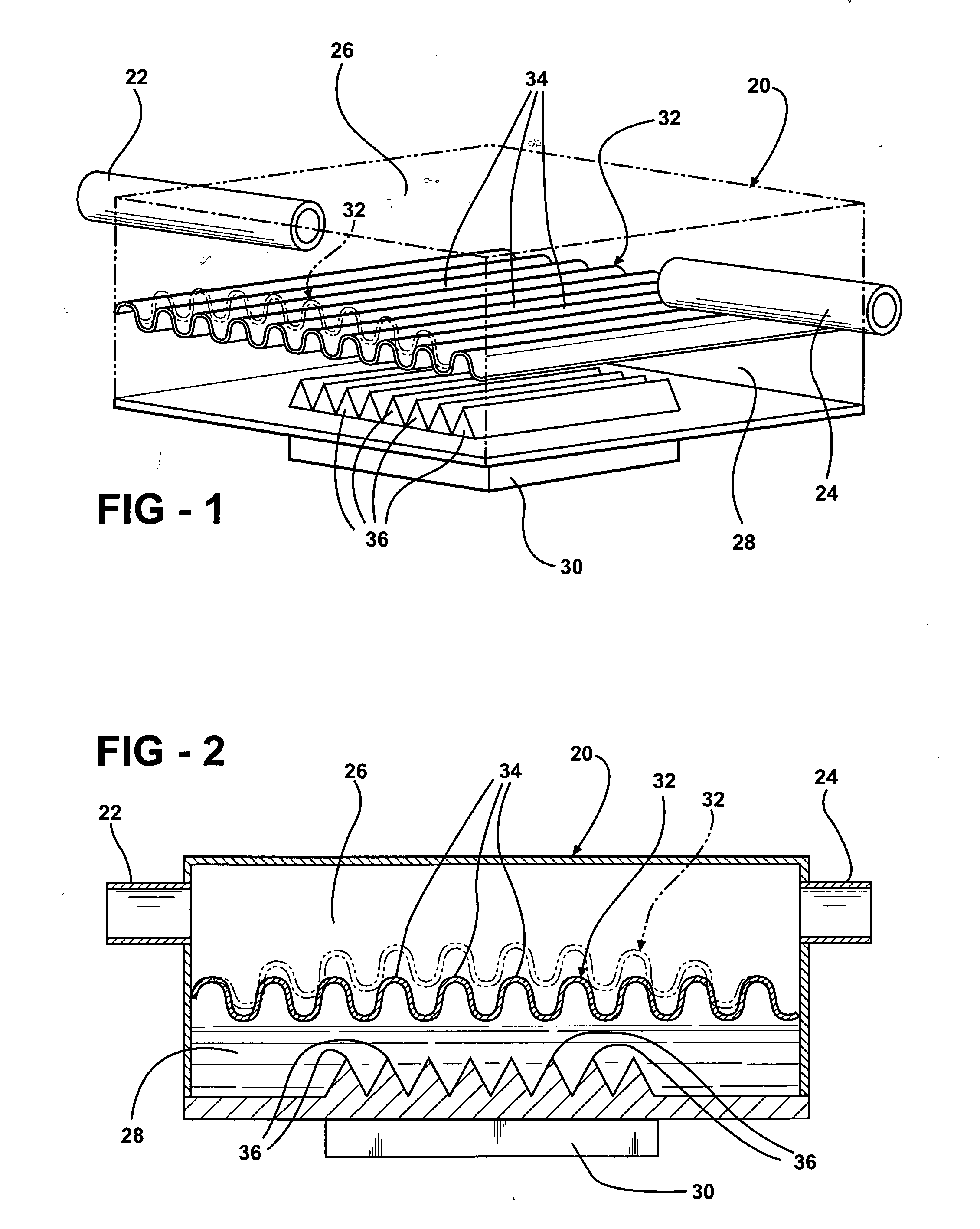
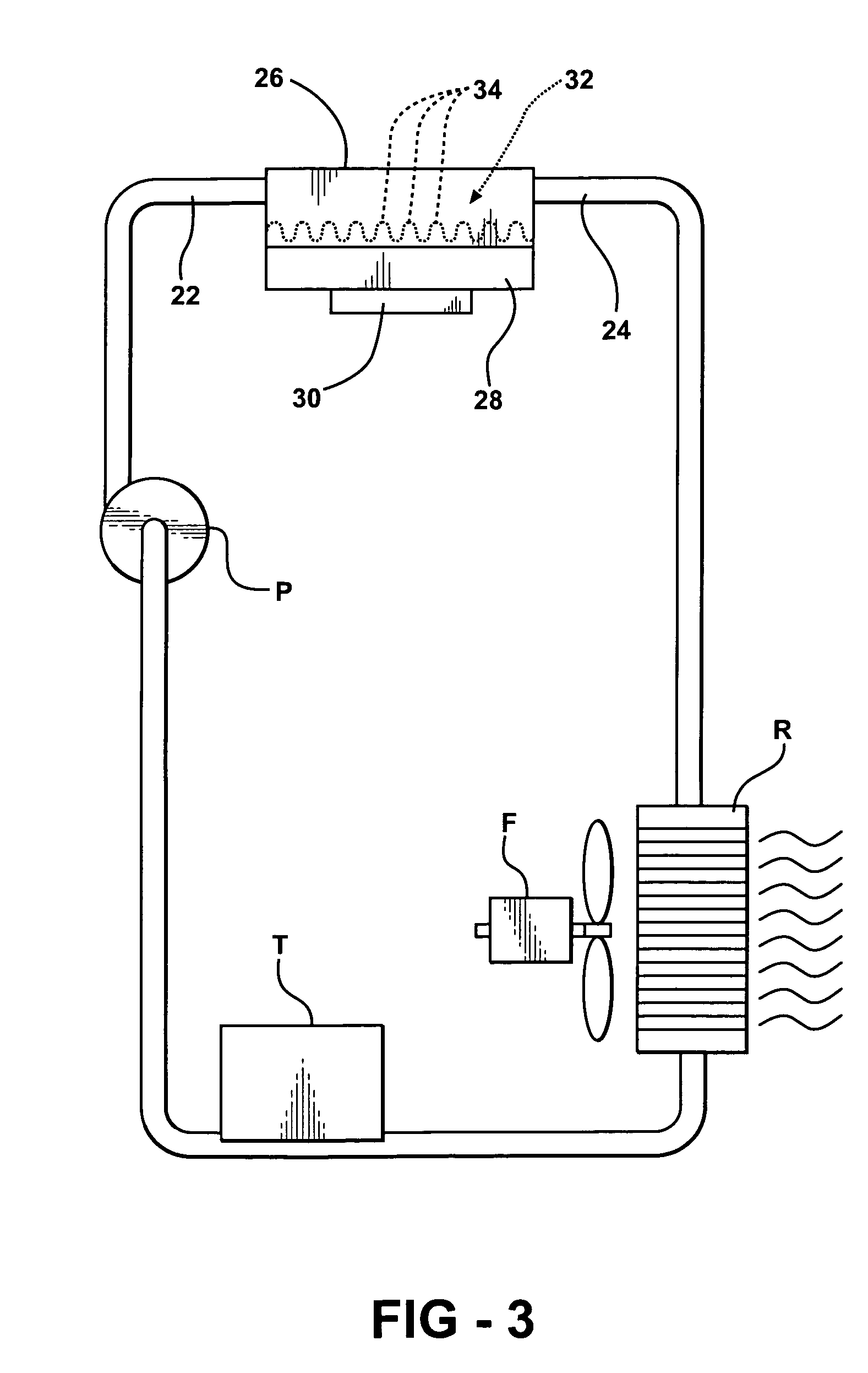
[0019] A fluid heat exchanger assembly comprises a housing 20 having an inlet 22 and an outlet 24 and an upper portion 26 and a lower portion 28 extending between the inlet 22 and the outlet 24 for establishing a direction of flow from the inlet 22 to the outlet 24. The assembly is used to cool an electronic device 30 engaging or secured to the lower portion 28 of the housing 20.

[0020] A partition 32 divides the housing 20 into the upper portion 26 and the lower portion 28 for establishing a direction of flow of coolant liquid from the inlet 22 to the outlet 24 in the upper portion 26.

[0021] The housing 20 is hermetically sealed about the partition 32 to contain a refrigerant in the lower portion 28 for liquid-to-vapor transformation. In other words, the partition 32 separates the refrigerant in the lower portion 28 from the coolant fluid in the upper portion 26. The partition 32 is flexible to vary the volume of the upper portion 26 for modulating the flow of coolant fluid throug...


PUM


Abstract

A fluid heat exchanger assembly cools an electronic device with a cooling fluid supplied from a heat extractor to an upper portion of a housing. A refrigerant is disposed in a lower portion of the housing for liquid-to-vapor transformation. A partition divides the upper portion of the housing from the lower portion and is flexible to vary the volume of the upper portion for modulating the flow of coolant fluid through the upper portion in response to heat transferred by an electronic device to the lower portion of the housing.

Description

RELATED APPLICATIONS [0001] The subject invention is related to the inventions disclosed in co-pending applications DP-311408 (H&H 60408-567) and DP-312789 (H&H 60408-597), filed concurrently herewith. BACKGROUND OF THE INVENTION [0002] 1. Field of the Invention [0003] A fluid heat exchanger assembly for cooling an electronic device. [0004] 2. Description of the Prior Art [0005] Research activities have focused on developing assemblies to efficiently dissipate heat from electronic devices that are highly concentrated heat sources, such as microprocessors and computer chips. These electronic devices typically have power densities in the range of about 5 to 35 W / cm2 and relatively small available space for placement of fans, heat exchangers, heat sink assemblies and the like. However, these electronic devices are increasingly being miniaturized and designed to achieve increased computing speeds that generate heat up to 200 W / cm2. [0006] Heat exchangers and heat sink assemblies have be...

Claims


Application Information

Patent Timeline
IPC IPC(8): H05K7/20
CPCF28D15/0266F28D15/06F28F3/12H01L23/427H01L2924/0002H01L23/473H01L2924/00
Inventor BHATTI, MOHINDER SINGHJOSHI, SHRIKANT MUKUNDPARISI, MARK JOSEPHJOHNSON, RUSSELL S.
Owner DELPHI TECH INC
Why Eureka
Try Eureka