

Piezoelectric thin-film resonator and method for producing piezoelectric thin film
a thin-film resonator and piezoelectric technology, applied in the field of piezoelectric thin-film resonators, can solve the problems of large absolute value of the temperature coefficient of frequency tcf of the piezoelectric thin-film device, difficult to vary the properties, and inability to obtain a piezoelectric thin-film device with a sufficient fractional bandwidth, etc., to achieve the expansion of the design scope of fractional bandwidth and frequency-temperature properties,
- Summary
- Abstract
- Description
- Claims
- Application Information
AI Technical Summary
Benefits of technology
Problems solved by technology
Method used
Image

Examples
first preferred embodiment
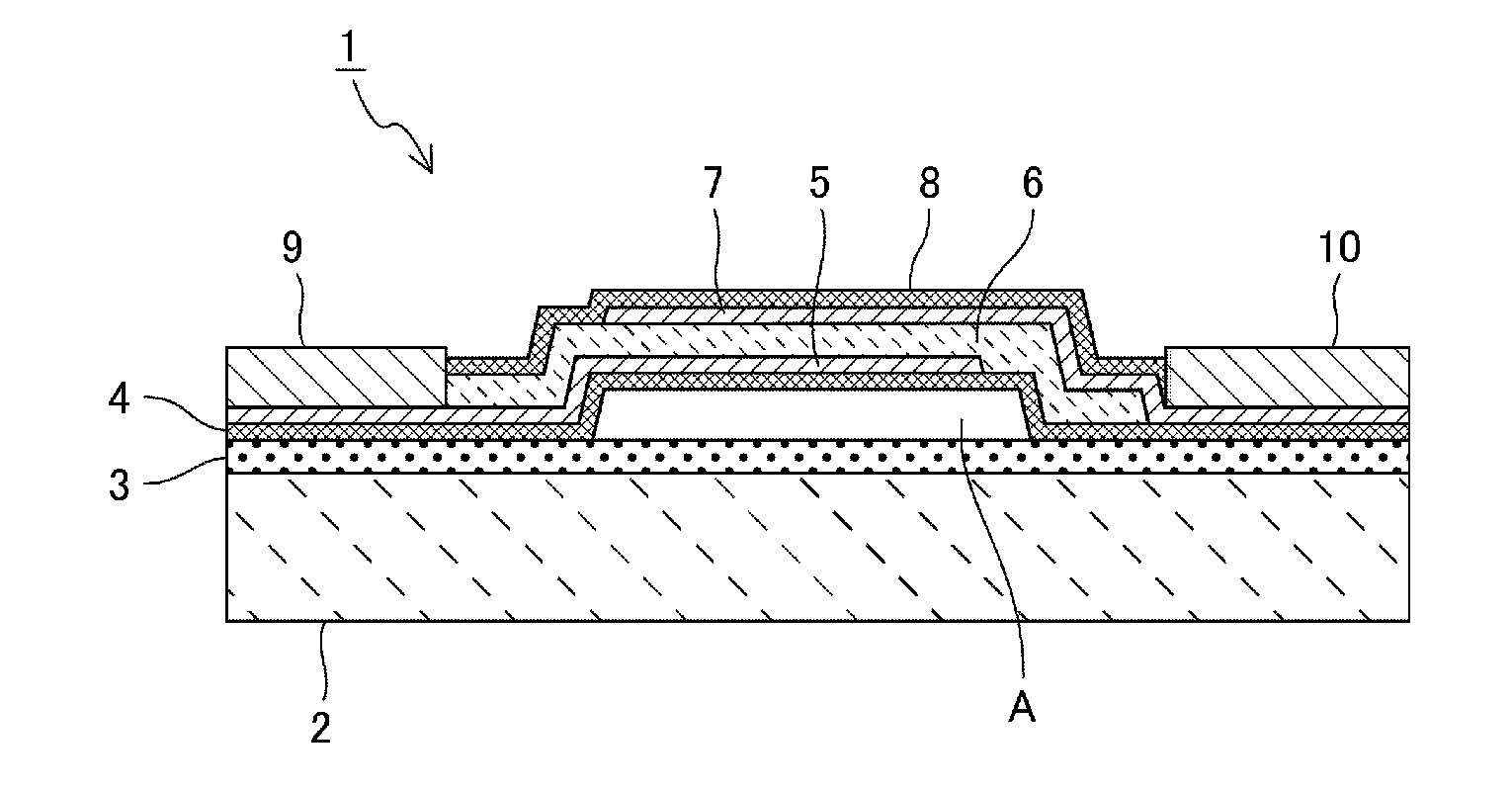
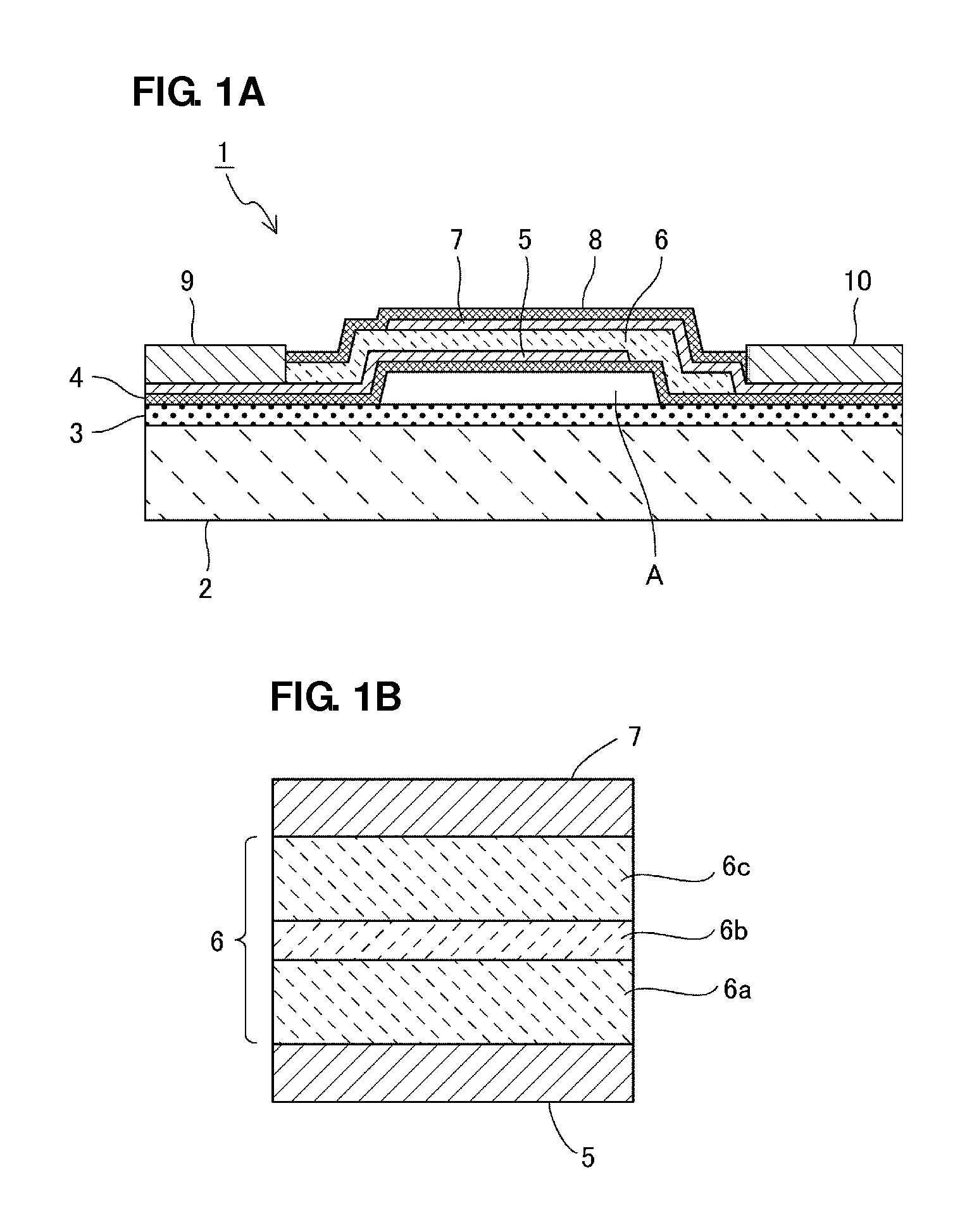
[0045]FIG. 1A is a front sectional view of a piezoelectric thin-film resonator 1 according to a first preferred embodiment of the present invention.
[0046]The piezoelectric thin-film resonator 1 includes a substrate 2. The substrate 2 may be made of an appropriate material such as high-resistance silicon, glass, or GaAs, for example. In the present preferred embodiment, the substrate 2 is preferably made of Si, for example.
[0047]The substrate 2 is overlaid with an insulating film 3. The insulating film 3, which need not necessarily be used, is used in a step of forming a cavity A described below and therefore is preferably placed thereon. In the present preferred embodiment, the insulating film 3 is preferably made of silicon oxide.
[0048]The insulating film 3 is overlaid with a first protective film 4 to protect a resonator portion. The first protective film 4 is preferably made of silicon oxide, for example. The first protective film 4 includes a central portion that is separated fr...
second preferred embodiment
[0080]FIG. 5A is an enlarged front sectional view of a principal portion of a region in which a piezoelectric thin film 6A, a first electrode 5, and a second electrode 7 included in a piezoelectric thin-film resonator according to a second preferred embodiment of the present invention are stacked. FIG. 5B is a graph illustrating the concentration distribution of Sc in a thickness direction of the piezoelectric thin film.
[0081]With reference to FIG. 5A, the first electrode 5 and the second electrode 7 face each other across the piezoelectric thin film 6A. Other components used in this preferred embodiment preferably are substantially the same as those described in the first preferred embodiment. Therefore, descriptions made with reference to FIG. 1A are incorporated herein and these components will not be described.
[0082]The piezoelectric thin-film resonator includes a piezoelectric thin film 6A that is made of aluminum nitride containing Sc and the concentration of Sc therein is dis...
third preferred embodiment
[0094]FIG. 7 is an enlarged front sectional view of a principal portion of a region in which a piezoelectric thin film 6B, a first electrode 5, and a second electrode 7 included in a piezoelectric thin-film resonator according to a third preferred embodiment of the present invention are stacked.
[0095]Components, other than the piezoelectric thin film 6B, used in the present preferred embodiment as well as the second preferred embodiment preferably are substantially the same as those described in the first preferred embodiment. Therefore, descriptions made with reference to FIG. 1A are incorporated herein and these components will not be described.
[0096]With reference to FIG. 7, the first and second electrodes 5 and 7 face each other across the piezoelectric thin film 6B. The piezoelectric thin film 6B includes a first Sc-containing aluminum nitride layer 6d, an aluminum nitride layer 6e, and a second Sc-containing aluminum nitride layer 6f stacked in that order. That is, in contrast...
PUM
 Abstract
Description
Claims
Application Information