Method, system and apparatus for an antenna

a technology of antennas and antenna components, applied in the direction of antennas, antenna feed intermediates, antenna details, etc., can solve the problems of interference to other components of the radio, monopole antennas present certain problems, and the battery power consumption is far less, so as to avoid distortion of match and pattern, excellent transition, and significant reduction of cable current

Inactive Publication Date: 2007-09-18
ALEREON
View PDF8 Cites 86 Cited by
  • Summary
  • Abstract
  • Description
  • Claims
  • Application Information

AI Technical Summary

Benefits of technology

[0015]Embodiments of the present invention may have certain advantages, including that the microstrip-coupled feed may an excellent transition from an unbalanced feed (e.g. coaxial line) to a balanced dipole structure so that cable currents are reduced significantly and distortions in the match and the pattern can thus be avoided.
[0016]Another technical advantage of embodiments of the present invention may be that, unlike typical UWB antennae, this antenna does not require a radio frequency (RF) connector to connect to a coaxial feed line. Therefore, the antenna does not require (though in some embodiments can include) a coax connector or an end launcher. Instead, the coax can attach directly to the antenna by soldering. Omitting this RF connector may reduce the cost and size of the antenna.
[0017]Additionally, embodiments of this invention may provide an antenna smaller than 6 mm by 30 mm and may not require any ground plane.

Problems solved by technology

For example, transferring a 1 Gbyte file full of vacation pictures from a digital camera to a computer take merely seconds with UWB compared to hours using other currently available, technologies (i.e. Bluetooth) and consume far less battery power in doing so.
However, monopole antennas present certain problems.
More specifically, monopole antennas, when placed over finite sized groundplanes may result in non-localized currents in these groundplanes which, in turn, could result in interference to other components of the radio with which these monopole antennas are being utilized.
Thus, there is a potential for UWB systems to interfere with television reception of those types of system.

Method used


Image

  • Method, system and apparatus for an antenna
  • Method, system and apparatus for an antenna
  • Method, system and apparatus for an antenna

Examples


Embodiment Construction

[0032]The invention and the various features and advantageous details thereof are explained more fully with reference to the nonlimiting embodiments that are illustrated in the accompanying drawings and detailed in the following description. Descriptions of well known starting materials, processing techniques, components and equipment are omitted so as not to unnecessarily obscure the invention in detail. Skilled artisans should understand, however, that the detailed description and the specific examples, while disclosing preferred embodiments of the invention, are given by way of illustration only and not by way of limitation. Various substitutions, modifications, additions or rearrangements within the scope of the underlying inventive concept(s) will become apparent to those skilled in the art after reading this disclosure.

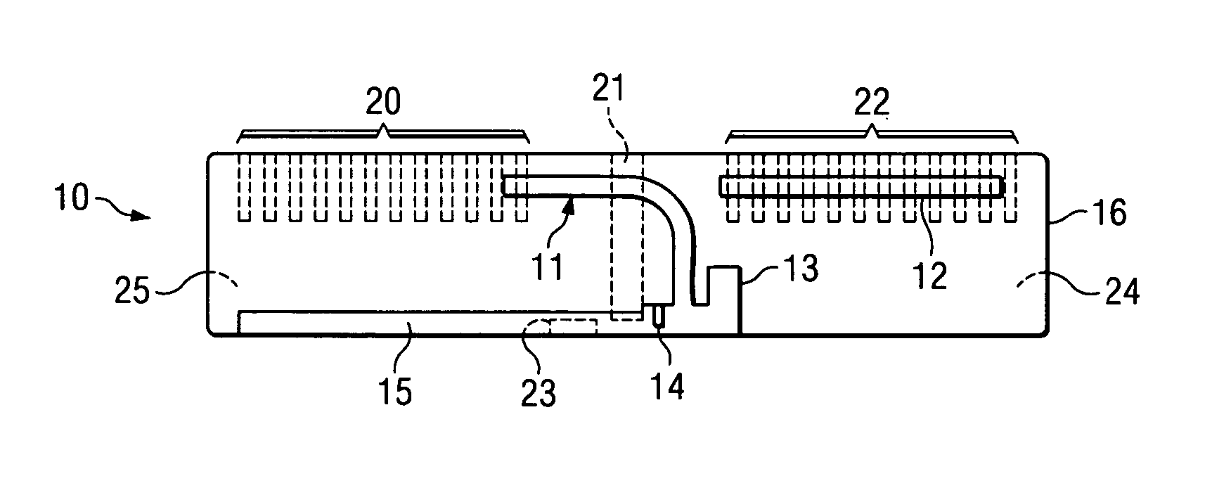
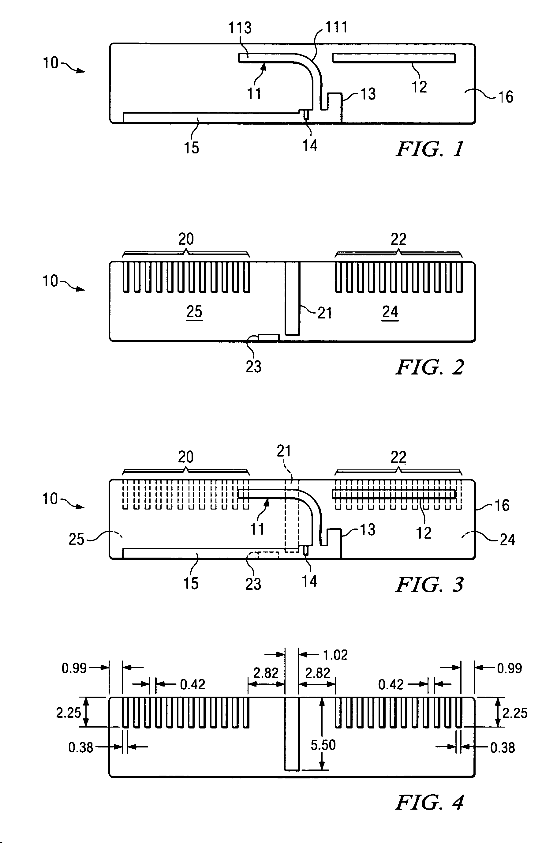
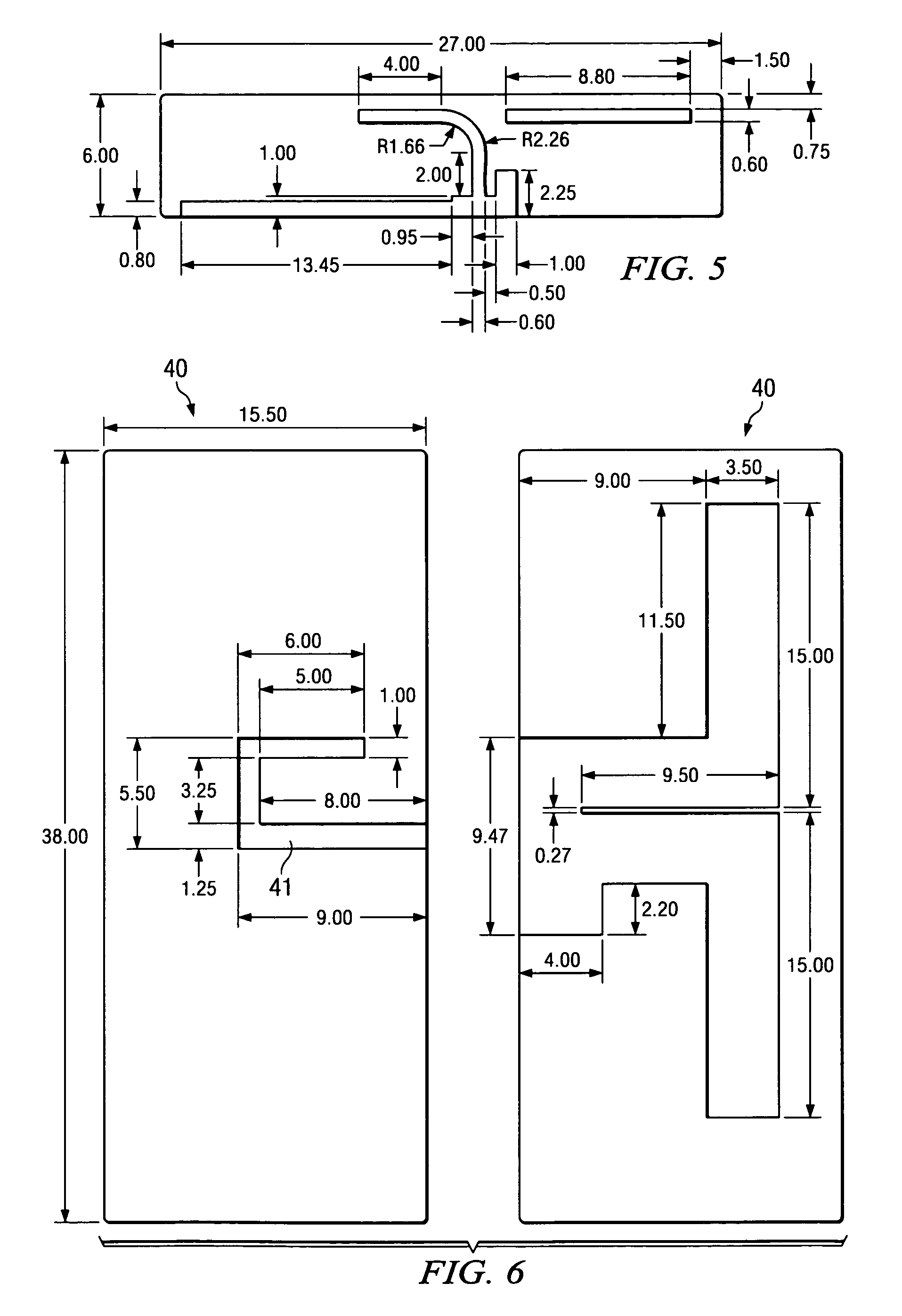
[0033]Attention is now directed to methods, systems and apparatuses for antennas, embodiments of which may be utilized with UWB devices. Embodiments of the pres...


PUM


Abstract

Embodiments of the present invention provide a microstrip-coupled dipole antenna. A microstrip of the antenna may be formed on top of a printed circuit board (PCB) and coupled to a transmission line such that the microstrip is operable to transfer electromagnetic energy fed to it by the transmission line to a dipole structure on the bottom of the PCB that, in turn, radiates a broadband electromagnetic signal.

Description

RELATED APPLICATIONS[0001]This application claims priority to U.S. Provisional Patent Application Ser. No. 60 / 695,645 by inventor Thorsten W. Hertel, entitled “Omnidirectional UWB Dipole Antenna with Built-In Notch Filters” filed on Jun. 30, 2005, the entire contents of which are hereby expressly incorporated by reference for all purposes.TECHNICAL FIELD OF THE INVENTION[0002]The invention relates in general to methods, systems and apparatuses for antennas. More particularly, the invention relates to methods, systems and apparatuses for ultra wideband (UWB) antennas. Even more particularly the invention relates to omnidirectional UWB antennas.BACKGROUND OF THE INVENTION[0003]Recently, wireless data, entertainment and mobile communications technologies have become increasingly prevalent, particularly in the household and computing environment. The convergence of these wireless data, entertainment and mobile communications within the home and elsewhere has created the need for merging...

Claims


Application Information

Patent Timeline
Patent Type & Authority Patents(United States)
IPC IPC(8): H01Q9/28
CPCH01Q9/065H01Q9/285
Inventor HERTEL, THORSTEN W.
Owner ALEREON
Why Eureka
Try Eureka