Space optical modulator

Inactive Publication Date: 2006-07-20
TDK CORPARATION
View PDF0 Cites 26 Cited by
  • Summary
  • Abstract
  • Description
  • Claims
  • Application Information

AI Technical Summary

Benefits of technology

[0019] (9) The spatial light modulator according to (6), (7), or (8) wherein the mask plate is able

Problems solved by technology

Because the variable focal point mirror mentioned above uses a silicone diaphragm, there are problems of time being required to switch the focal length and poor responsiveness.
There are also problems of the need t

Method used


Image

  • Space optical modulator
  • Space optical modulator
  • Space optical modulator

Examples


Embodiment Construction

[0033] In the following, exemplary embodiments of the present invention will be described in detail.

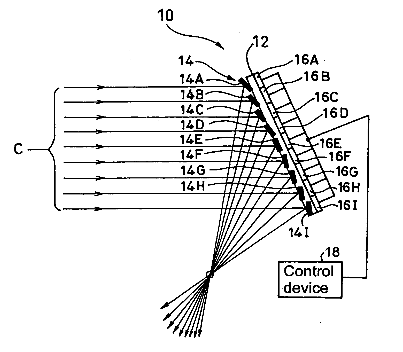
[0034] As shown in FIGS. 1 (A) and (B), the spatial light modulator 10 (hereinafter referred to as SLM) according to example 1 of the exemplary embodiment of the present invention is a device that is configured by arranging a plurality of micro mirrors 14A, 14B, 14C, - - - , 14I on a substrate 12 in an array configuration corresponding to memory cells 16A, 16B, 16C, - - - , 16I and that selectively changes between one of two reflection angle states of each of the micro mirrors 14A, 14B, 14C, - - - by applying or releasing an electrostatic attracting force exerted between the memory cells 16A, 16B, 16C, - - - . As shown in FIG. 1 (A), for one of the two reflection angle states mentioned above a micro mirror array 14, composed of the micro mirrors 14A, 14B, 14C, - - - , is provided with a reflection angle distribution to reflect incident collimated light C to be converged at one point ...


PUM


Abstract

A spatial light modulator that can quickly switch the focal length and light intensity distribution. This spatial light modulator 10 has a plurality of micro mirrors 14A, 14B, 14C, - - - arranged on a substrate 12 and these micro mirrors 14A, 14B, 14C - - - are each provided with a reflection angle distribution such that they converge the reflected light at one point for one reflection angle state with respect to incident collimated light and such that the reflected light is diverged for the other reflection angle state.

Description

TECHNICAL FIELD [0001] The present invention relates to a spatial light modulator that uses a micro mirror array to allow a variable focal point or adjust the light intensity distribution. BACKGROUND ART [0002] From the past many different variable focal point optical elements with a function to adjust the focal lengths in the optical elements themselves have been proposed. [0003] From among these types of variable focal point optical elements, there is a variable focal point mirror that provides a film thickness distribution to a silicone diaphragm and forms a paraboloid shaped concave mirror with a variable focal length. [0004] In addition, conventionally it was necessary to uniformly modulate the light intensity distribution for incident light with a Gaussian light intensity distribution. [0005] Because the variable focal point mirror mentioned above uses a silicone diaphragm, there are problems of time being required to switch the focal length and poor responsiveness. [0006] The...

Claims


Application Information

Patent Timeline
IPC IPC(8): G02B5/08G02B26/02G02B26/08
CPCG02B26/0833
Inventor TSUKAGOSHI, TAKUYAYOSHINARI, JIRO
Owner TDK CORPARATION
Why Eureka
Try Eureka