
Method and apparatus for controlling a neural stimulus

a neural response and stimulus technology, applied in the field of neural response control, can solve the problems of unfavorable patient safety, unfavorable patient safety, and difficulty in maintaining appropriate stimulus amplitude, so as to avoid misalignment of induced paraesthesia and control the neural recruitment level

Active Publication Date: 2014-08-21
SALUDA MEDICAL
View PDF1 Cites 146 Cited by
  • Summary
  • Abstract
  • Description
  • Claims
  • Application Information

AI Technical Summary

Benefits of technology

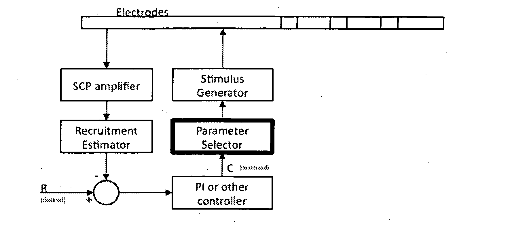
The patent describes a system to control the rate at which a control variable, such as an electrical stimulation, changes in response to user percepts. This allows for a more comfortable and natural response to sudden changes in postural changes. The system also adapts the stimulus parameters based on the user's postural changes, using a feedback variable that measures the evoked response amplitude or the position of fast neural peaks. This leads to more effective and efficient stimulation, and can help avoid misalignment of induced paraesthesia. Overall, the system ensures a controlled and comfortable experience for the user while promoting effective therapy outcomes.

Problems solved by technology

While the clinical effect of spinal cord stimulation (SCS) is well established, the precise mechanisms involved are poorly understood.
In almost all neuromodulation applications, a single class of fibre response is desired, but the stimulus waveforms employed can recruit other classes of fibres which cause unwanted side effects, such as muscle contraction if motor fibres are recruited.
The task of maintaining appropriate stimulus amplitude is made more difficult by electrode migration and / or postural changes of the implant recipient, either of which can significantly alter the neural recruitment arising from a given stimulus, depending on whether the stimulus is applied before or after the change in electrode position or user posture.
Postural changes alone can cause a comfortable and effective stimulus regime to become either ineffectual or painful.
A control problem, facing neuromodulation systems of all types, is achieving neural recruitment at a sufficient level required for therapeutic effect, but at minimal expenditure of energy.
The power consumption of the stimulation paradigm has a direct effect on battery requirements which in turn affects the device's physical size and lifetime.
For rechargeable systems, increased power consumption results in more frequent charging and, given that batteries only permit a limited number of charging cycles, ultimately this reduces the lifetime of the device.

Method used


Image

  • Method and apparatus for controlling a neural stimulus
  • Method and apparatus for controlling a neural stimulus
  • Method and apparatus for controlling a neural stimulus

Examples


first embodiment

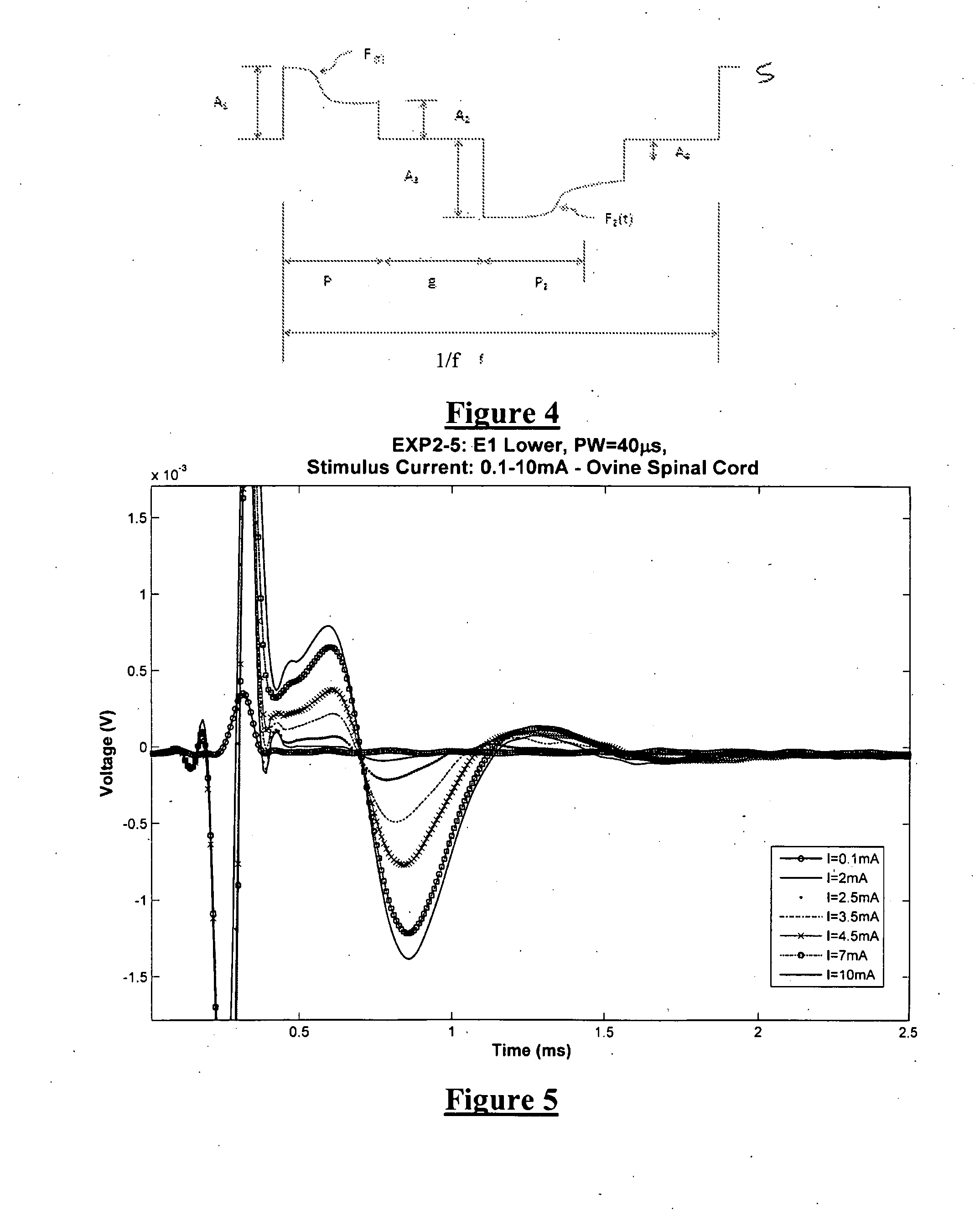
[0114]A first embodiment for estimating recruitment in the presence of varying electrode-to-fibre distance d, is based on relative amplitudes found in measurements at two electrodes. The amplitude of the evoked response varies with the applied charge and the response can be measured on a number of different electrodes distant from the electrode where the stimulus is applied. The responses measured in the sheep spinal cord are shown in FIG. 8, for responses in the ascending direction (i.e. for electrodes positioned away from the stimulating electrode along the midline of the spinal cord). FIG. 14a displays the variation in evoked SCP amplitude with Varying stimulus current, on four separate electrodes in the ascending direction, while FIG. 14b showing the equivalent in the descending direction. In particular, FIG. 14 shows ascending and descending evoked CAP N1-P2 amplitudes, recorded in sheep in response to biphasic 40 μs stimulus pulse widths.

[0115]The amplitude of the responses fo...

second embodiment

[0119]A second embodiment for estimating neural recruitment in the presence of varying electrode-to-fibre distance d, is based on a two point method. The evoked response measured on one electrode has an almost linear dependence on the applied current, in the operating region between threshold and saturation and for a given stimulation pulse width. The response changes (independent of pulse width) with applied charge. If we consider two response curves at two different postures P1 and P2, then they will have different amplitude and saturation point, which will depend on the separation of the electrode from the tissue in each respective posture.

[0120]For a fixed electrical activity in the spinal cord the effect of moving the sense electrode away will be to scale the response curve by the factor which relates to the separation. The electrical activity however changes because in this case the sense electrode and the stimulating electrode are both moving with respect to the spinal cord. ...


PUM


Abstract

An implantable device applies and controls a neural stimulus. The device has a plurality of electrodes, and a stimulus source for providing a stimulus to be delivered from the electrodes to a neural pathway in order to evoke an action potential on the neural pathway, such as the spinal cord. A control unit controls application of a neural stimulus as defined by a set of parameter values and measures via measurement circuitry an evoked neural compound action potential response. The control unit determines from the measured evoked response a feedback variable, and compares it to a therapy map. The therapy map defines a therapeutic relationship of control variable to feedback variable. One or more of the stimulus parameter values are altered to effect the required change in the control variable. This process is performed iteratively to improve alignment of the feedback variable with the therapy map over time.

Description

CROSS-REFERENCE TO RELATED APPLICATIONS[0001]This application claims the benefit of Australian Provisional Patent Application No. 2011901829 filed 13 May 2011, Australian Provisional Patent Application No. 2011901817 filed 13 May 2011, Australian Provisional Patent Application No. 2011901821 filed 13 May 2011 and Australian Provisional Patent Application No. 2011901827 filed 13 May 2011, each of which are incorporated herein by reference.TECHNICAL FIELD[0002]The present invention relates to controlling a neural response to a stimulus, and in particular relates to measurement of a compound action potential by using one or more electrodes implanted proximal to the neural pathway, in order to provide feedback to control subsequently applied stimuli.BACKGROUND OF THE INVENTION[0003]There are a range of situations in which it is desirable to apply neural stimuli in order to give rise to a compound action potential (CAP). For example, neuromodulation is used to treat a variety of disorder...

Claims


Application Information

Patent Timeline
IPC IPC(8): A61N1/36A61B5/296
CPCA61N1/36071A61B5/4041A61B5/4821A61B5/4824A61B5/4836A61N1/0551A61N1/36139A61B5/407A61N1/3615A61B5/24A61B5/388
Inventor PARKER, JOHN LOUISLAIRD, JAMES HAMILTONKARANTONIS, DEAN MICHAELOBRADOVIC, MILAN
Owner SALUDA MEDICAL
Learn More