Camera snubber assembly

a technology for snubbers and cameras, applied in the field of snubbers, can solve the problems of limiting the use of snubbers in low light conditions, affecting the focusing effect, and limiting the resolution of stopping down, so as to facilitate focusing and/or zooming

Active Publication Date: 2010-01-12
DIGITALPTICS MEMS
View PDF13 Cites 56 Cited by
  • Summary
  • Abstract
  • Description
  • Claims
  • Application Information

AI Technical Summary

Benefits of technology

[0008]For example, the snubber assembly can readily permit movement in one translational degree of freedom while substantially limiting motion in the other five degrees of freedom. This is accomplished in a manner that facilitates focusing and / or zooming of a camera while inhibiting misalignment of the optics and while also providing some protection against shock and vibration.
[0009]Such motion control can be achieved while mitigating the costs associated with precision manufacturing of the snubber assembly. More particularly, the precision with which manufacturing of the snubber assembly is performed can be reduced by relying upon physical features of a stage assembly to facilitate precise positioning of physical features of the snubber assembly. That is, positioning of at least some features of the snubber assembly are dependent upon corresponding features of the stage assembly such that desirable alignment of the snubber assembly with respect to the stage assembly results.
[0013]According to one aspect of the present invention, smaller features of the snubber assembly are manufactured with higher tolerances, while larger features of the snubber assembly can be manufactured with lower tolerances. It is not necessary to manufacture larger features of the snubber assembly with higher tolerances and thus manufacturing costs are therefore substantially reduced.

Problems solved by technology

However, such stopping down of the camera severely limits it's use in low light conditions.
Stopping down also limits resolution since it tends to inhibit the use of higher pixel count imagers.
However, movable optics suffer from inherent disadvantages.
Foremost among these disadvantages is the size of the mechanisms required to effect and control movement of the movable optics.
For example, the structures used to control the movement of optics in larger cameras are simply too large for use in many miniature cameras.

Method used


Image

  • Camera snubber assembly
  • Camera snubber assembly
  • Camera snubber assembly

Examples


Embodiment Construction

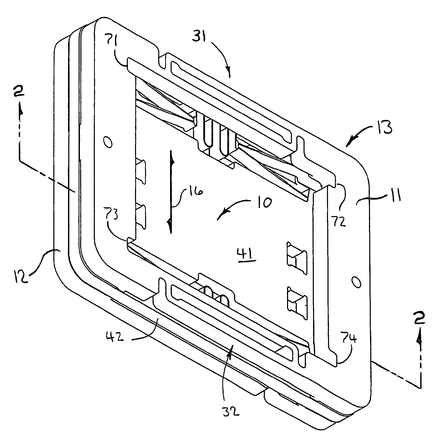
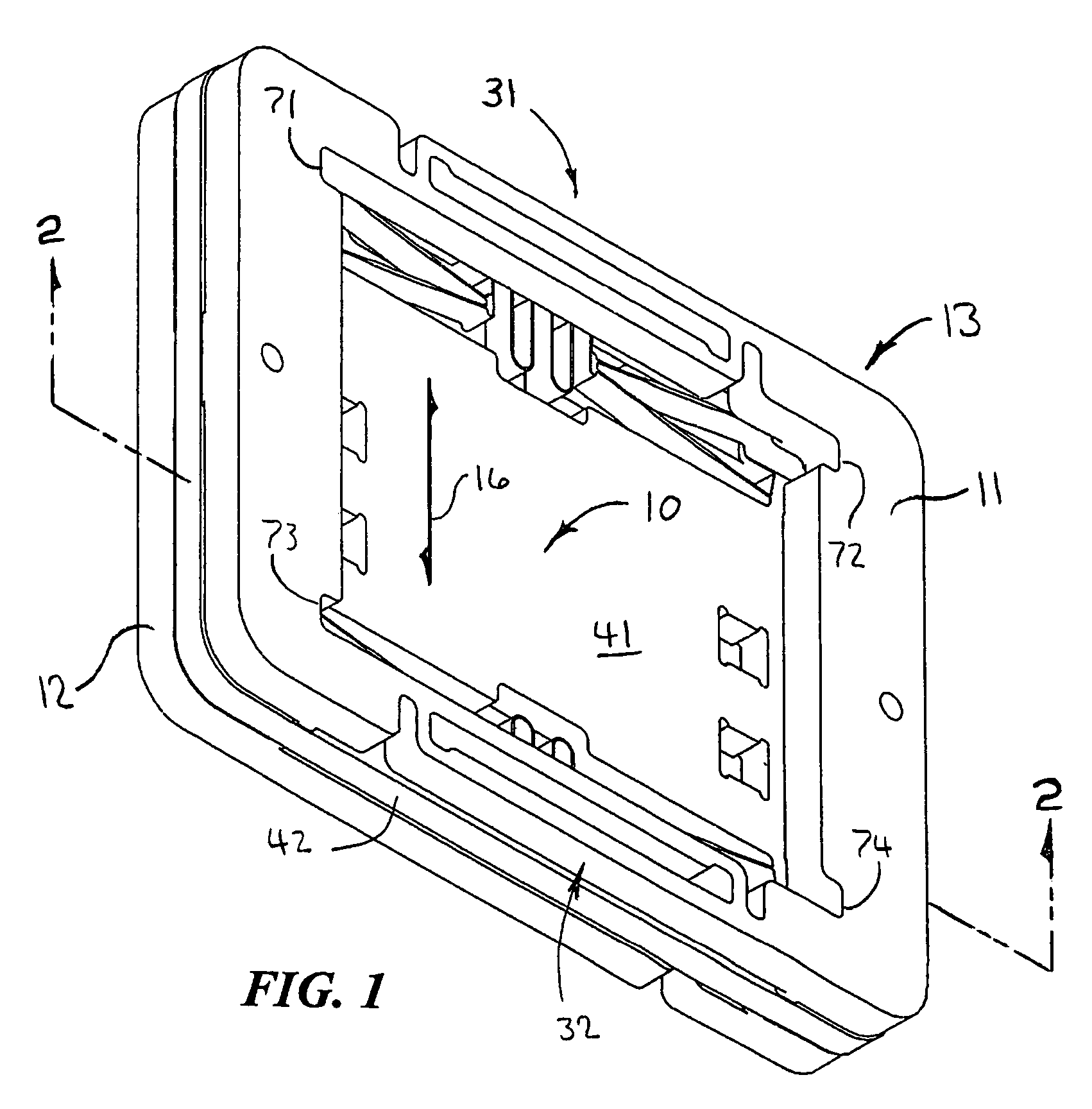
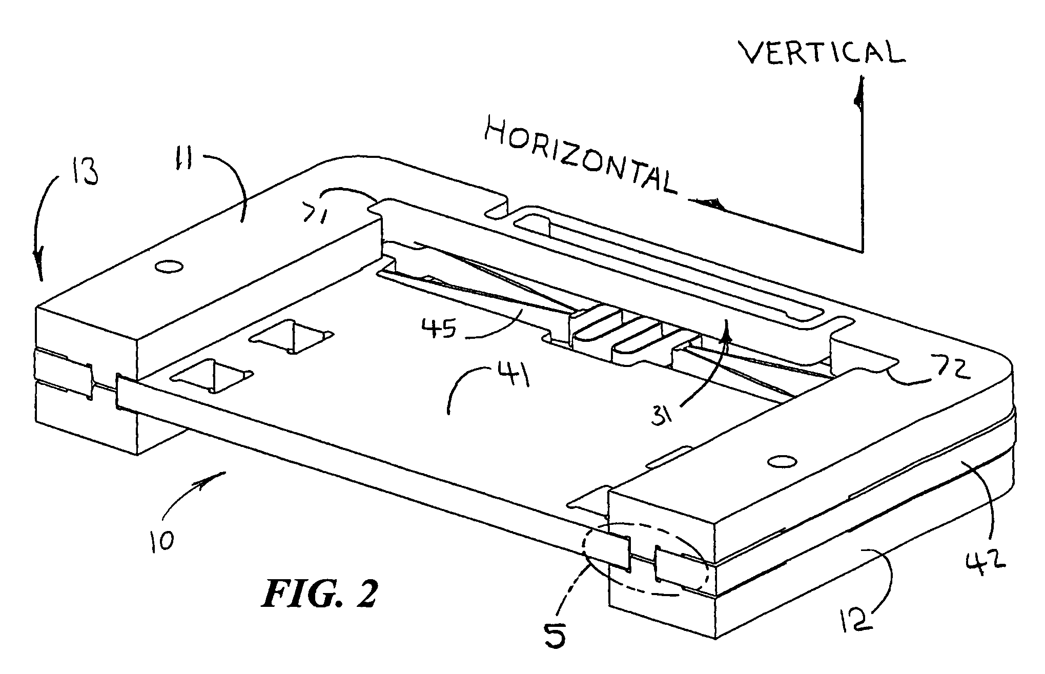
[0022]A method and system for defining the motion of a stage is disclosed. The stage is suitable for mounting camera optics upon. For example, focus and / or zoom lenses can be mounted to the stage. According to one aspect of the present invention, motion of the stage in six degrees of freedom is controlled. More particularly, motion in five degrees of freedom is substantially limited, while motion in one translational degree is freedom is facilitated. For example, translational motion in two degrees of freedom can be limited to approximately 10 microns, rotational motion in three degrees of freedom can be limited to approximately 0.1 degrees, and translational motion in one degree of freedom in excess of one millimeter can be facilitated.

[0023]In this manner, the stage can be permitted to translate along one axis sufficiently so as to effect focusing and / or zooming, while not being permitted to translate sufficiently along other axes or to rotate about any axis sufficiently so as to ...


PUM


Abstract

A method and system for limiting the motion of components such as the optics of a camera are disclosed. The system can comprise a stage and a snubber assembly for controlling motion of the stage in six degrees of freedom. For example, the snubber assembly can permit movement in one translational degree of freedom while substantially limiting motion in the other five degrees of motion so as to facilitate focusing and / or zooming of a camera while inhibiting misalignment of the optics and while providing some protection against shock and vibration. Such motion control can be achieved while mitigating costs associated with precision manufacturing of the snubber assembly.

Description

PRIORITY CLAIM[0001]This patent application claims the benefit of the priority date of U.S. provisional patent application Ser. No. 60 / 657,261, filed on Feb. 28, 2005 and entitled AUTOFOCUS CAMERA pursuant to 35 USC 119. The entire contents of this provisional patent application are hereby expressly incorporated by reference.TECHNICAL FIELD[0002]The present invention relates generally to cameras. The present invention relates more particularly to a snubber assembly for limiting the motion of optical elements in a miniature camera, such as a miniature camera that is suitable for use in a cellular telephone.BACKGROUND[0003]Miniature cameras are well known. Miniature cameras are widely used in contemporary cellular telephones. They are also used in other devices, such as laptop computers and personal digital assistants (PDAs). Miniature cameras can even be used as stand alone devices for such applications as security and surveillance.[0004]Contemporary miniature cameras, such as those ...

Claims


Application Information

Patent Timeline
Patent Type & Authority Patents(United States)
IPC IPC(8): G03B17/00G02B7/02
CPCG02B7/003G02B7/023G03B3/02G03B17/02H04N5/2251H04N23/50
Inventor CALVET, ROBERT J.GUTIERREZ, ROMAN C.JAYARAJ, KUMARASWAMYNGO, TIM QUANG-TINH
Owner DIGITALPTICS MEMS
Why Eureka
Try Eureka