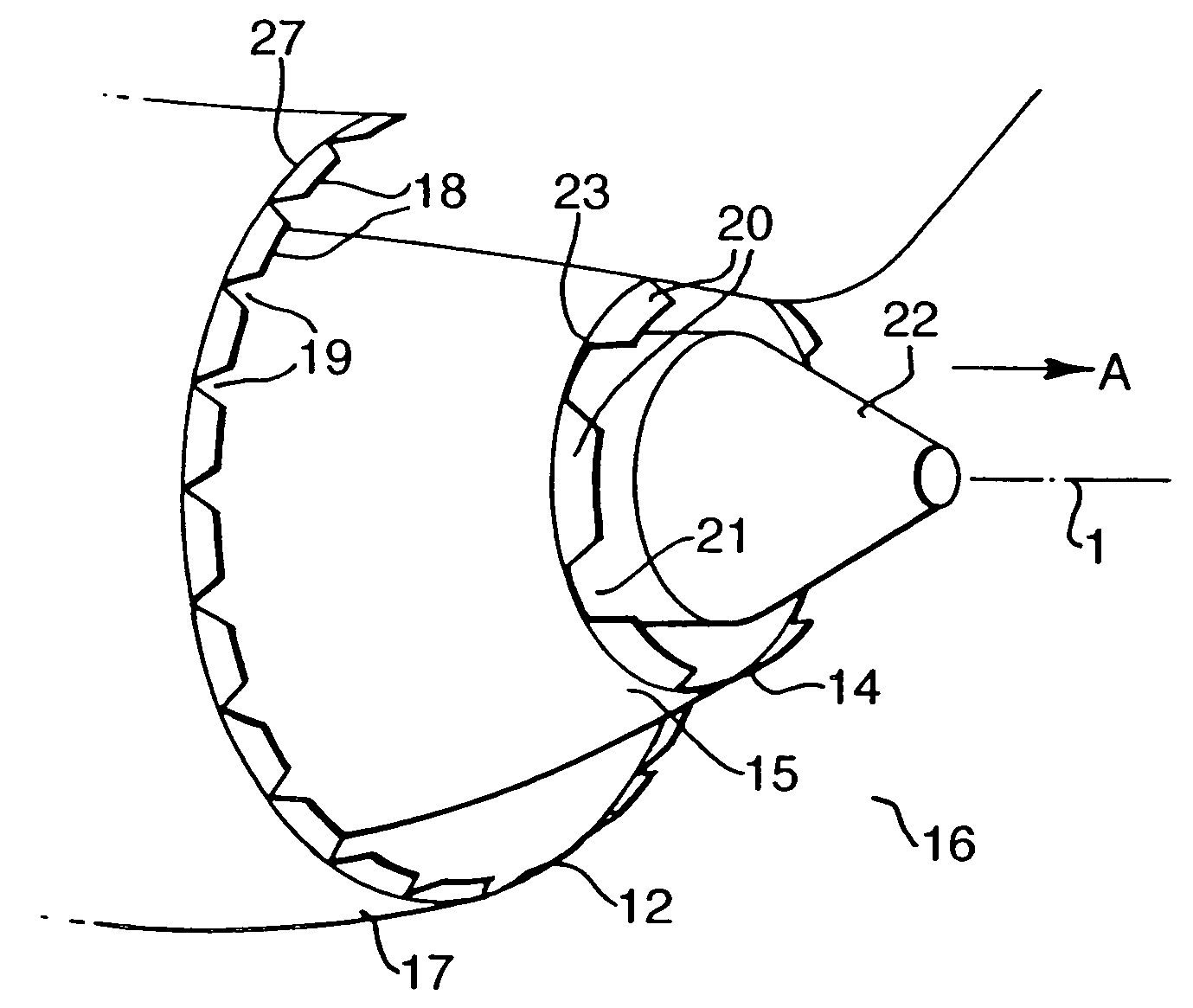
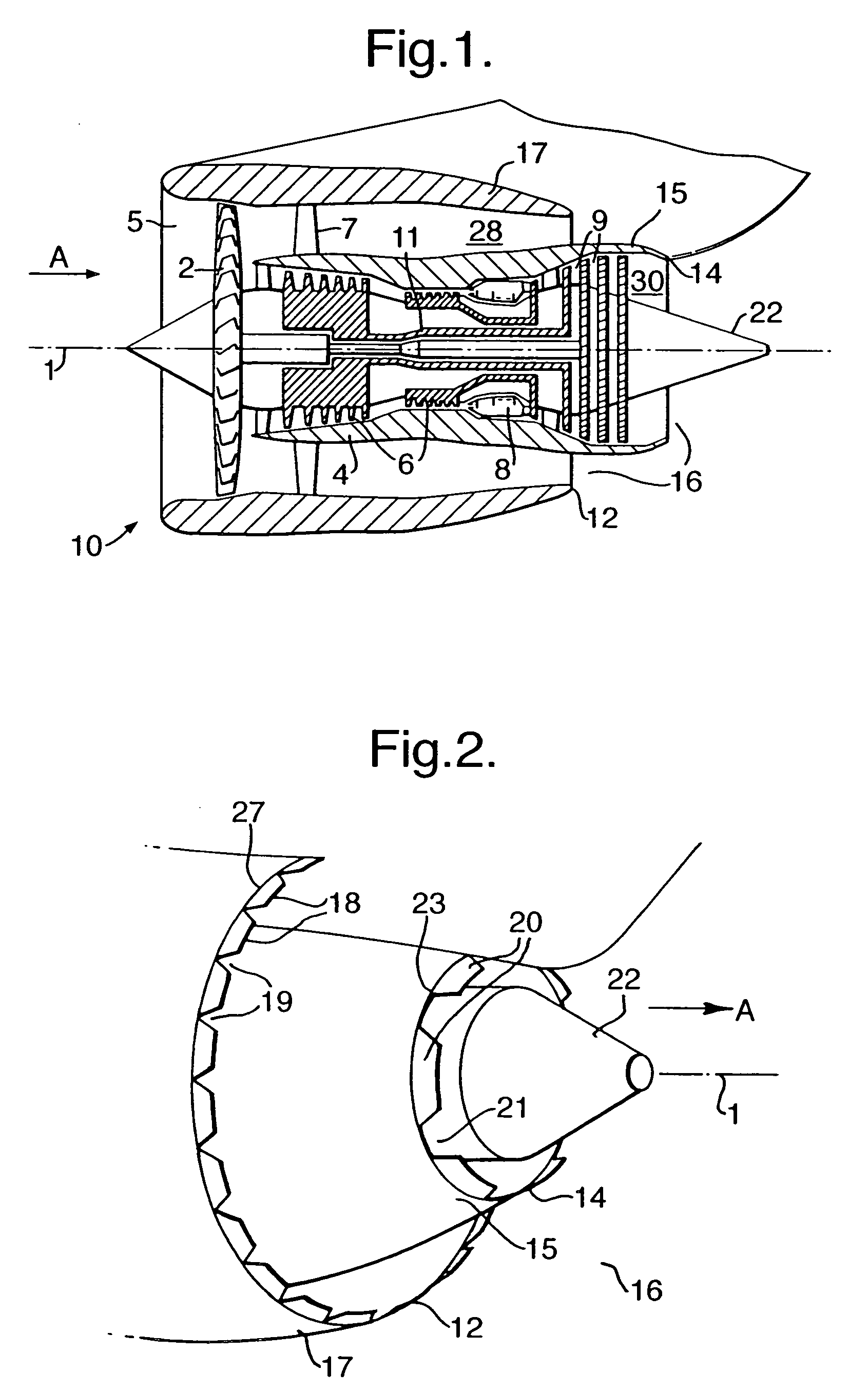
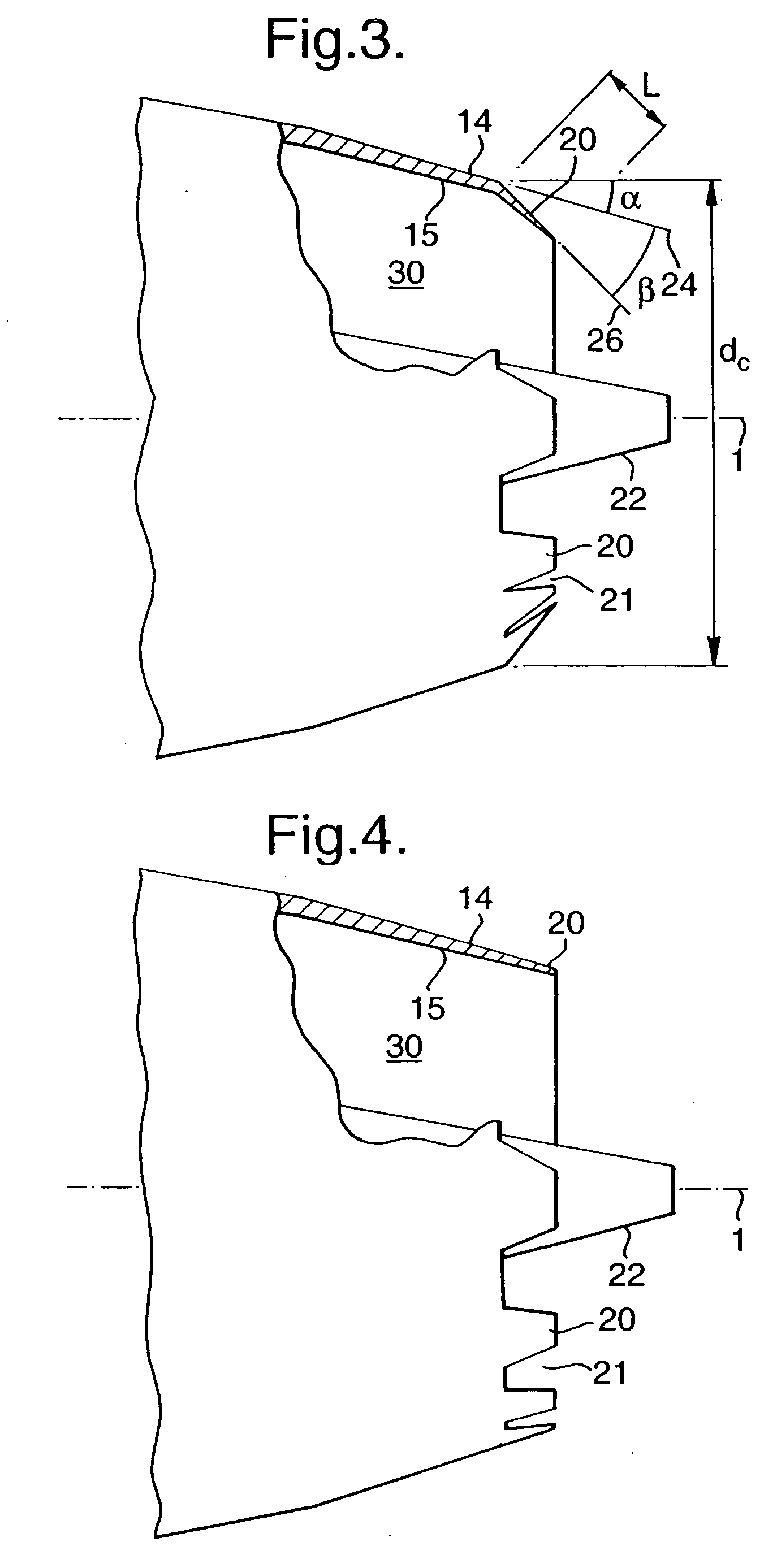
Gas turbine engine exhaust nozzle

a gas turbine engine and exhaust nozzle technology, applied in the direction of machines/engines, climate sustainability, sustainable transportation, etc., can solve the problems of noise generation, noise generation, and noise generation in the core exhaust stream of the gas turbine engine, and achieve the effect of reducing the noise of the exhaust stream

Inactive Publication Date: 2005-10-20
ROLLS ROYCE PLC
View PDF22 Cites 154 Cited by
  • Summary
  • Abstract
  • Description
  • Claims
  • Application Information

AI Technical Summary

Benefits of technology

[0014] It is therefore desirable and is an object of the present invention to provide an improved gas turbine engine exhaust nozzle which is quieter than conventional exhaust nozzles and / or which offers improvements generally.
[0015] Another object of the present invention is to provide a high stiffness and high deflection mechanism that uses SMM's, which can be designed to operate substantially in bending against external loads and is also inherently robust and lightweight.
[0016] According to a first aspect of the present invention there is provided a gas turbine engine exhaust nozzle arrangement for the flow of exhaust gases therethrough between an upstream end and a downstream end thereof comprising a nozzle, a downstream portion and a plurality of tabs, each tab extends in a generally axial direction from the downstream portion of the nozzle wherein the nozzle further comprises an actuation mechanism capable of moving the tabs between a first deployed position, in the first position the tabs interact with a gas stream to reduce exhaust noise thereof, and a second non-deployed position, in the second position the tabs are substantially aerodynamically unobtrusive.
[0026] Preferably, the tab defines an orifice, the orifice exposed to a gas stream, and a passage, the passage extending from the orifice, to the shape memory material and thereby provides a conduit for rapidly transmitting changes in the thermal flux of the gas stream to and throughout the memory shape material element.

Problems solved by technology

The high velocity gas stream produced by gas turbine engines generates a significant amount of noise, which is referred to as exhaust or jet noise.
This noise is generated due to the high velocity of the exhaust stream, or streams, and the mixing of the streams with the surrounding atmosphere, and in the case of two streams, as the bypass and core streams mix.
This is because the core stream velocity is considerably greater than the bypass stream and also the surrounding atmosphere and consequently the core exhaust stream generates a significant amount of the exhaust noise.
Mixing of the core stream with the bypass stream has also been found to generate a significant proportion of the exhaust noise due to the difference in velocity of the core and bypass streams.
However, this adds considerable weight, drag, and cost to the installation and nowadays short bypass nozzles are favoured with which the lobed type core nozzles are less effective and are also more detrimental to the engine performance than when used on a long cowl arrangement.
However the parameters and details of the design proposed in GB 2,289,921 are not optimal and there is a continual desire to improve the nozzle design further.
However, the main requirement of reducing exhaust noise is during aircraft take-off and landing.
More than two conditions could be useful, but suitable materials are not currently known.
The use of discrete wires severely limits the volume of material which can be utilised, which limits the total energy that can be expended and the integrity of the structure.
Intimate contact between the SMA and parent structure (as in U.S. Pat. No. 6,718,752) severely limits the overall strain that can be achieved because the parent engineering material preferably is subject to a strain similar to that of the SMM.
This leads to severe compromises between the deflection that can be achieved and the stiffness of the structure as it opposes external (operational) loads.
To achieve large deflections it must be thin, but this results in a low stiffness such that the SMM can be bent easily by external loads such as air, liquid etc.

Method used


Image

  • Gas turbine engine exhaust nozzle
  • Gas turbine engine exhaust nozzle
  • Gas turbine engine exhaust nozzle

Examples


first embodiment

[0099]FIG. 5 shows the present invention, the nozzle comprising a suitable mechanism for deploying the tabs 20. The deployable tabs 20 are shown in the second non-deployed position by the solid lines, where they are generally aligned with the nozzle wall 15 and therefore aligned generally with the exhausted gas stream, and in the first deployed position by the dashed tabs 20′. In the first deployed position the tabs 20′ interact with the gas stream creating and shedding noise reducing vortices. The first mechanism 32 suitable for activating the tabs 20, 20′ comprises a shape memory material (SMM) element 34, as known in the art, which is switchable from a first shape indicated as reference numeral 34 to a second shape indicated as reference numeral 34′. The SMA element 34 is disposed within or partly within a pocket 36 situated in the aft end of the nozzle wall 15 and a recess 38 in the tab 20. The SMM element 34 is secured by rotatable means 40, 42 to both the nozzle wall 15 and th...

second embodiment

[0104]FIG. 6 is a section through part of the core nozzle 14 and shows the present invention, the nozzle 14 comprising a second actuation mechanism 50 for deploying the tabs 20. The second actuation mechanism 50 is disposed within or partly within a pocket 36 situated in the aft end of the nozzle wall 15 and a recess 38 in the tab 20 and comprises a SMM spring element 52, in the general form of a helical spring, and a further, coaxial spring 54. The coaxial spring 54 comprises a conventional resilient material and which operates in a conventional manner. The SMM spring 52 may be secured by rotatable means 56, 58 to both the nozzle wall 15 and the tab 20 respectively. The second mechanism 50 also comprises the tab 20 being rotatably mounted to the nozzle wall 15 by further rotatable means 60.

[0105] The second embodiment of the present invention operates in a similar manner to the first embodiment in that the length of the SMM spring element 52 changes when its temperature is above or...

third embodiment

[0108]FIG. 7 is a section through the part of the core nozzle 14 and shows the present invention, the nozzle comprising a third actuation mechanism for deploying the tabs 20. The deployable tabs 20 are shown in the second non-deployed position by the solid lines, where they are generally aligned with the nozzle wall 15 and therefore aligned generally with the exhausted gas stream, and in the first deployed position by the dashed tabs 20′. In the first deployed position the tabs 20′ interact with the gas stream generating and shedding noise-reducing vortices.

[0109] In this third embodiment of the present invention the tabs 20 themselves are manufactured from SMM thus the tabs themselves are the actuation mechanism. The tab 20 is disposed to the periphery of the nozzle 14 and generally extends in the rearward direction therefrom. Again above the switch temperature the SMM tab 20′ will be in the first deployed position and below the switch temperature the SMM tab 20 will be in the seco...


PUM


Abstract

A gas turbine engine exhaust nozzle arrangement for the flow of exhaust gases therethrough between an upstream end and a downstream end thereof comprising a nozzle and a plurality of tabs which extend in a generally axial direction from a downstream portion of the nozzle wherein the nozzle further comprises an actuation mechanism capable of moving the tabs between a first deployed position, where the tabs interact with a gas stream to reduce exhaust noise thereof, and a second non-deployed position, where the tabs are substantially aerodynamically unobtrusive.

Description

[0001] This application is a Continuation-in-Part of U.S. patent application Ser. No. 10 / 950,551, filed Sep. 28, 2004, which claims priority to U.S. patent application Ser. No. 10 / 072,990, filed Feb. 12, 2002, now U.S. Pat. No. 6,813,877, issued Nov. 19, 2004, which claims priority to United Kingdom patent Appl'n No. 0105349.5, filed Mar. 3, 2001, the complete disclosures of which are incorporated herein by reference.FIELD OF INVENTION [0002] The present invention relates generally to gas turbine engine exhaust nozzles, and in particular to noise reduction and performance improvements to nozzle arrangements used for gas turbine engines suited to aircraft propulsion. BACKGROUND [0003] Gas turbine engines are widely used to power aircraft. As is well known, the engine basically provides propulsive power by generating a high velocity stream of gas which is exhausted rearwards through an exhaust nozzle. A single high velocity gas stream is produced by a turbojet gas turbine engine. More...

Claims


Application Information

Patent Timeline
Patent Type & Authority Applications(United States)
IPC IPC(8): F02K1/38F02K1/42F02K1/46F02K3/02
CPCF02K1/383Y02T50/67F02K1/46F02K1/42F05D2300/505Y02T50/60
Inventor WEBSTER, JOHN R.
Owner ROLLS ROYCE PLC
Why Eureka
Try Eureka