Electric heating device for rail vehicle and rail vehicle

A rail vehicle and electric heating device technology, applied in the field of rail vehicles, can solve the problems that the side plate and bottom plate of the electric heater cannot be ventilated, affect the comfort of passengers, and the air convection effect is not good, so as to avoid excessive seat temperature, Good air convection effect, solve the effect of high heating power

Active Publication Date: 2015-04-29
CRRC QINGDAO SIFANG CO LTD
View PDF7 Cites 8 Cited by
  • Summary
  • Abstract
  • Description
  • Claims
  • Application Information

AI Technical Summary

Problems solved by technology

[0004] In the installation structure of the above-mentioned electric heater, the electric heater is installed close to the side wall and the floor, so that the side and bottom plates of the electric heater cannot be ventilated, the heat dissipation efficiency is greatly affected, and the air convection effect is not good.
In addition, due to the upward flow of hot air, the hot air heated by the electric heating tube will flow to the top of the electric heater, and accumulate in the inside of the cover plate to make the temperature of the heating chamber too high. There is a certain distance between the seat frames, but the distance is limited, the heat will still make the temperature of the seat higher, affecting the comfort of passengers

Method used


Image

  • Electric heating device for rail vehicle and rail vehicle
  • Electric heating device for rail vehicle and rail vehicle

Examples


Embodiment 1

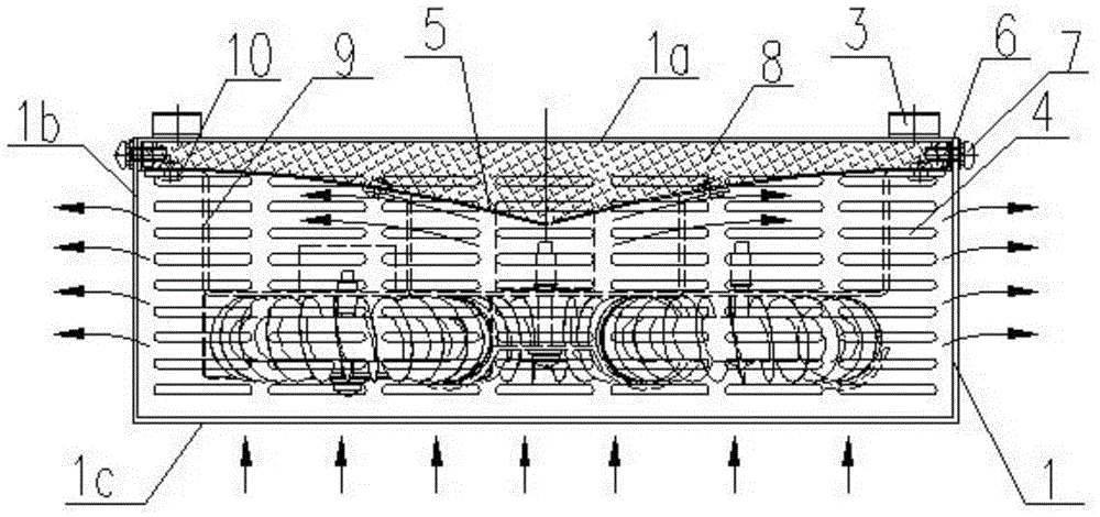
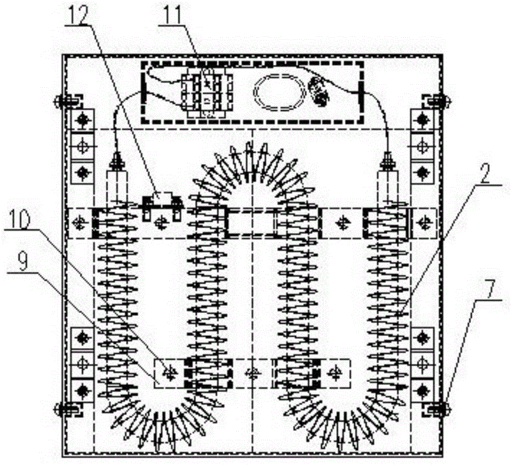
[0031] Such as figure 1 and figure 2 As shown, the electric heating device provided by the present invention includes a casing 1, and an electric heating element 2 is installed inside the casing 1. The casing 1 is composed of a top plate 1a, four side plates 1b and a bottom plate 1c. The top plate 1a, four side plates 1b and the bottom plate 1c can be fixedly connected together by screws, or the four side plates 1b and the bottom plate 1c can be integrally formed or welded together, and the top plate 1a can be fixedly connected with the side plate 1b separately to facilitate installation and maintenance.

[0032] On the upper surface of the top plate 1a of the cover shell 1, a plurality of mounting seats 3 are welded and installed, and the mounting seats 3 are fixedly connected with the seat frame (not shown in the figure) by bolts, and then the electric heating device is hung below the seat frame , the installation is very simple and convenient.

[0033] On the four side p...

Embodiment 2

[0044] The difference from Embodiment 1 is that the casing 1 does not have a top plate 1a, but the deflector 5 with flanges 6 around it and the top plate 1a of the casing 1 are separately integrated into a structural member with a cavity inside. The cavity is filled with heat insulating material 7, and then the entire structure filled with heat insulating material 7 is fixed on the side plate 1b of the casing 1 by bolts, so that during installation, repair and maintenance, the body of the casing 1 The top plate 1a, the deflector 5 and the heat insulating material 7 are disassembled and installed as a whole, which is convenient and quick.


PUM


Abstract

The invention relates to an electric heating device for a rail vehicle and the rail vehicle. The electric heating device comprises a cover case, wherein an electric heating element is arranged inside the cover case, the cover case is hung under a seat, a heat insulation layer is arranged on the inner wall of a top plate of the cover case, and ventilation openings are respectively formed in four side plates and a bottom plate of the cover case. The electric heating device is hang under the seat, the structure is compact, the space in the vehicle is not occupied, the integral attractive appearance in the vehicle is not influenced, in addition, the four side surfaces and the bottom surface of the electric heating device are respectively provided with the ventilation openings, and the air inlet from the bottom and the air outlet from the four side surfaces are realized, so that the air convection effect of the electric heating device is better, heat can be more easily radiated into the vehicle, the heat radiation efficiency is high, meanwhile, through the arrangement of the heat insulation layer, the too-high temperature of the seat is effectively avoided, and the taking comfort is ensured.

Description

technical field [0001] The invention relates to an electric heating device used for heating in winter, in particular to an electric heating device used on a rail vehicle, and at the same time relates to a rail vehicle equipped with the electric heating device. Background technique [0002] Electric heating devices are installed in rail vehicles such as EMUs and urban express lines for heating in winter. Traditional electric heating devices are installed between the side wall panels and the side walls of the car body, and some electric heating devices are installed on the side walls. bottom outside of the board. For the 140-kilometer city express electric passenger car, due to the small gap between the inner wall panel and the side wall of the car body, it is impossible to arrange the traditional electric heating device. [0003] In order to solve this problem, in the prior art, the form of installing the electric heating device under the seat is adopted, such as the Chinese...

Claims


Application Information

Patent Timeline
Patent Type & Authority Applications(China)
IPC IPC(8): B61D27/00
CPCB61D27/0045Y02T30/00
Inventor 何文辉焦玉翠刘慧峰姜鸿鹏张克姝路娜龚明
Owner CRRC QINGDAO SIFANG CO LTD
Why Eureka
Try Eureka