Building drainage concentrator

A technology for building drainage and concentrators, which is applied in kitchen drainage concentrators, balconies, and bathrooms. It can solve the problems of easy drying of floor drain water seals, difficult maintenance, and easy blockage of pipes, and achieve the effect of improving drainage capacity.

Active Publication Date: 2015-06-10
贵州群之英屋业科技有限公司
View PDF6 Cites 1 Cited by
  • Summary
  • Abstract
  • Description
  • Claims
  • Application Information

AI Technical Summary

Problems solved by technology

[0002] At present, when floor drains are installed in bathrooms, kitchens, and balconies on the same floor of the building, floor drains must be lowered or partially lowered. Air, harmful gases, bugs, etc. are easy to run into the room and affect the living and hygienic environment

Method used


Image

  • Building drainage concentrator
  • Building drainage concentrator
  • Building drainage concentrator

Examples


Embodiment 1

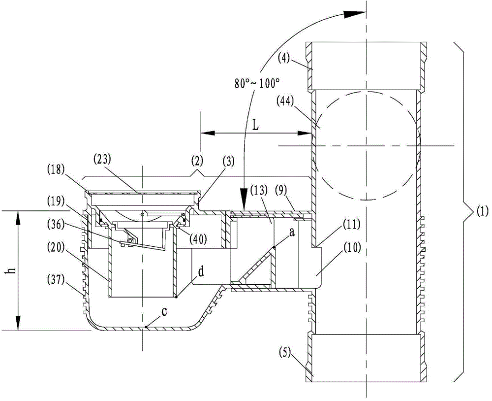
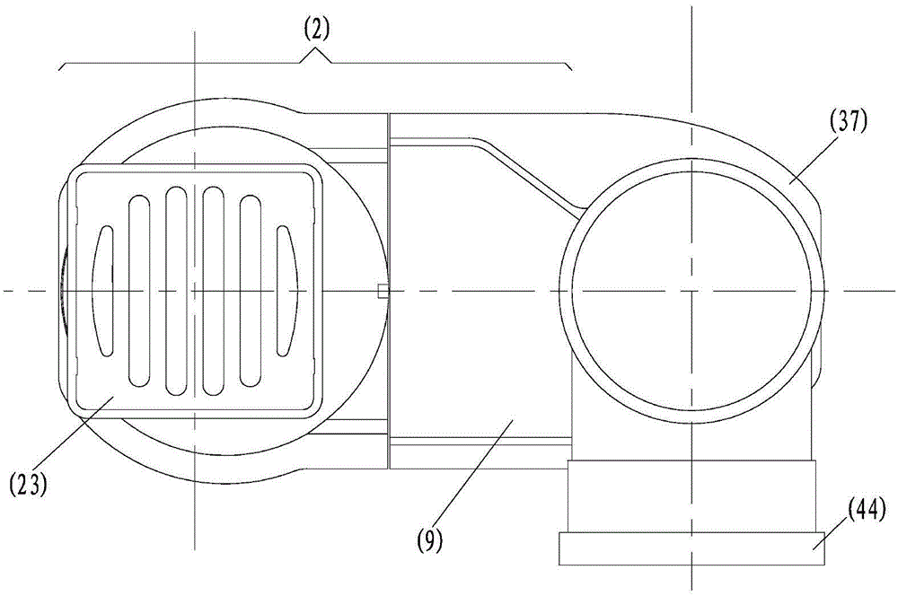
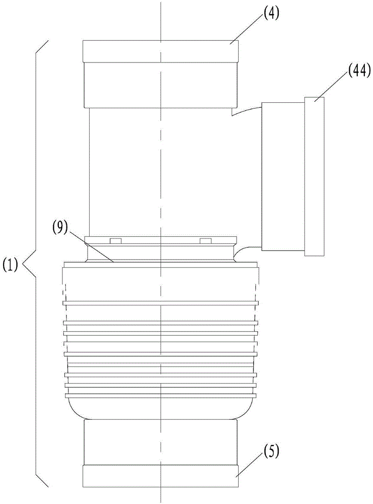
[0029] Such as figure 1 , 2 , 3, 4, and 5, the building drainage concentrator according to the present invention is composed of a vertical pipe drainage section (1), a horizontal pipe drainage collection section (2) and a water seal member (3). The vertical pipe drainage section (1) is connected up and down; the horizontal pipe drainage collection section (2) is located on one side of the vertical pipe drainage section (1), and the hollow part is connected with the hollow part of the vertical pipe drainage section (1). The horizontal surface (9) of the collection section (2) and the lower inner wall are planes, and the included angle with the upper interface (4) of the riser drainage section (1) is 90°; the horizontal pipe drainage collection section (2) and the standpipe The cross-sectional area of ​​the opening (10) at the connection of the drainage section (1) is 3000mm 2 The horizontal pipe drainage converging section (2) connected to the standpipe drainage section (1) h...

Embodiment 2

[0031] Such as Figure 6 As shown, the lower part (20) and the middle part (19) of the water sealing body component of the building drainage collector according to the present invention are not integral components, and the inner diameter of the lower end (31) of the middle part (19) of the water sealing body is larger than The outer diameter of the lower end of the lower part of the water sealing member (20) is smaller than the outer diameter of the upper end (33) of the lower part of the water sealing member (20), and there are grooves (34) on the outer wall of the upper end (33) of the lower part of the water sealing member (20). ), there is a rubber ring (35) in the groove (34), and the rubber ring (35) is located in the inner wall of the middle part (19) of the water seal member; Pull out the lower part (20) of the water seal member from the middle part (19) of the water seal member (there is a handle on the upper end (33) of the lower part of the water seal member (20)), ...

Embodiment 3

[0033] Such as Figure 6 , 7As shown, the lower part (20) of the water seal component (20) and the middle part (19) of the water seal component of the high-rise building bathroom drainage collector according to the present invention are not integral components, and the inner diameter of the lower end (31) of the middle part (19) of the water seal component The outer diameter of the lower part (20) of the water sealing member is 68 mm, the outer diameter of the upper end (33) of the lower part (20) of the water sealing member is 86 mm, and the upper surface of the lower end (31) of the middle part (19) of the water sealing member It is in contact with the lower surface of the upper end (33) of the lower part (20) of the water seal member, and both are plane. There are 2 grooves (39) on the lower end (31) of the middle part (19) of the water seal member, and the diameter of the groove is 76mm, the arc length is 10mm, there are 2 bumps (40) on the outer wall of the lower part of...


PUM


Abstract

A building drainage concentrator relates to a drainage concentrator applied to toilets, balconies and kitchens. The building drainage concentrator consists of a stand pipe drainage section (1), a horizontal pipe drainage concentrating section (2) and a water seal component (3). A horizontal surface (9) of the horizontal pipe drainage concentrating section (2) and an inner wall below are planes or cambered surfaces approximate to planes. A maximum distance of a horizontal opening (15) of a channel (13) on the top of the concentrating section of the horizontal pipe drainage concentrating section (2) that is communicated with the stand pipe drainage section (1) is greater than a maximum distance of a vertical opening (16). The top of the water seal component (3) on one side of the horizontal surface (9) is communicated with the bottom of the water seal component; a floor drain cover (23) is arranged above the water seal component. The minimal distance L between the outside of the upper portion (18) of the water seal component and the outer wall of the adjacent stand pipe drainage section is ranging from 40mm to 450mm. The lowest end at the inlet of a horizontal pipe port (44) is higher than the horizontal surface (9). In case of the floor drains are installed, the building drainage concentrator is able to use the toilet, the kitchen and the balcony when the water is drained at the same floor of the building, without any fall slabs or slightly descending floors.

Description

technical field [0001] The invention relates to a drainage collector for buildings, in particular to a drainage collector for toilets, balconies and kitchens. Background technique [0002] At present, when floor drains are installed in bathrooms, kitchens, and balconies on the same floor of the building, floor drains must be lowered or partially lowered. Gas, harmful gas, small insects, etc. are easy to run into the room and affect the living and hygienic environment. Contents of the invention [0003] The purpose of the present invention is to overcome the existing technical defects, to provide a kind of use toilet, kitchen, balcony in the same floor drainage in the building without any lowering floor or micro-lowering board, the pipeline below the drainage device is not easy to block, It is easy to overhaul, and the water seal of the floor drain is not easy to dry up, making it difficult for odor, harmful gas, and small insects to enter the room, and it is a building dr...

Claims


Application Information

Patent Timeline
Patent Type & Authority Applications(China)
IPC IPC(8): E03C1/122
Inventor 林国强程宏伟邱寿华
Owner 贵州群之英屋业科技有限公司
Why Eureka
Try Eureka