

Method and apparatus for transmitting messages
A transmission method and equipment technology, applied in the field of communication, can solve the problems of traffic interruption, message sending, no communication, etc.
- Summary
- Abstract
- Description
- Claims
- Application Information
AI Technical Summary
Problems solved by technology
Method used
Image

Examples
Embodiment Construction
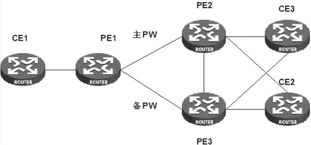
[0029] Aiming at the problems existing in the prior art, the embodiment of the present invention provides a message transmission method, which is applied in a VPLS network, such as a VPLS multi-CE device dual-homing master-standby PW networking, and multiple CE Devices (two or more CE devices) are dual-homed to the same two PE devices at the same time. These two PE devices are the first PE device and the second PE device. Based on this, multiple CE devices are dual-homed For the first PE device and the second PE device. Wherein, the link between the first PE device and the third PE device, the link between the second PE device and the third PE device are the active PW and the backup PW respectively, for example, the first PE device and the third PE device The link between the two PEs is the primary PW, and the link between the second PE and the third PE is the standby PW; or, the link between the first PE and the third PE is the standby PW, and the second PE The link between ...
PUM
 Abstract
Description
Claims
Application Information