Beam pumping unit

A beam pumping unit and beam beam technology are applied in wellbore/well components, production fluid, earthwork drilling and production, etc., which can solve problems such as the inability to automatically adjust the position of the center of gravity of the balance block at any time, difficulty in smooth flow of lubricating oil, and oil pumping. The machine can not work normally and other problems, to achieve the effect of small balance torque, fast heating speed, and reduce energy consumption

Inactive Publication Date: 2019-01-08
SICHUAN JINXIN CO LTD
View PDF7 Cites 0 Cited by
  • Summary
  • Abstract
  • Description
  • Claims
  • Application Information

AI Technical Summary

Problems solved by technology

2. There is a counterweight balance block on the crank. When the donkey head of the pumping unit is at the upper and lower dead center positions, the position of the balance block is below or above the nearest axis of the torque driven shaft, and the resulting balance moment is the smallest. The dynamic load acceleration at the upper and lower dead centers of the pump is at the maximum, and the donkey head of the pumping unit bears the maximum dynamic load, and the required balance torque also needs to be the largest. At this time, it depends on the energy consumed by the motor to overcome it, so the pumping unit must use a high-power motor Only in this way can the pumping unit be driven, which further leads to higher energy consumption of the motor
3. The beam-balanced pumping unit is designed with a certain offset angle and distance of the center of gravity of the balance block. When the pumping unit is running, the position of the center of gravity of the balance block cannot be automatically adjusted at any time, but the pumping unit is at the upper and lower dead centers. position to obtain the maximum or minimum balance moment
However, due to the large water content of some types of oil and gas, their adhesion is small, and the operation of ultra-low strokes (0.18~9 times / min) is required to successfully extract oil and gas, and the pumping unit is working in the field, especially in Xinjiang. In Karamay Oilfield and other places, the winter temperature is very low, and the lowest outdoor temperature can be as low as -30~0°C. At this time, the lubricating oil in the reducer box is in a viscous or frozen state, and the lubricating oil in the box is difficult to flow smoothly. flow, correspondingly reduces the amount of lubricating oil splashed by the gear meshing, resulting in poor lubrication effect of the bearing, which in turn causes the pumping unit to fail to work normally

Method used


Image

  • Beam pumping unit
  • Beam pumping unit
  • Beam pumping unit

Examples


Embodiment 1

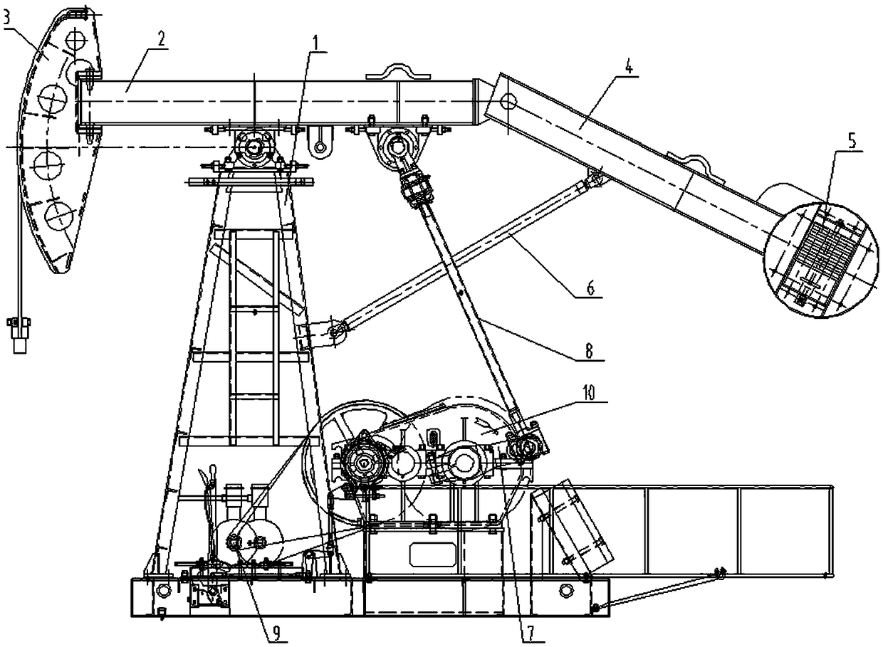
[0031]A beam pumping unit, comprising a bracket 1, a motor 9, a reducer 10, a crank 7, a connecting rod 8, a beam 2, a donkey head 3, a constant temperature heater 17, a balance arm 4, a balance weight 5 and a support rod 6. The traveling beam 2 is movably connected to the bracket 1, the donkey head 3 is fixed on one end of the traveling beam 2, the balance arm 4 is movably connected to the other end of the traveling beam 2, and the balance weight 5 is fixed on the balance On the arm 4, one end of the support rod 6 is movably connected to the bracket 1, and the other end is movably connected to the balance arm 4, and the beam 2 cooperates with the support rod 6 to drive the balance weight 5 to swing; the motor 9 and the reducer 10 connected, the reducer 10 is connected with the crank 7 to drive the crank 7 to rotate, the connecting rod 8 is movably connected between the crank 7 and the beam 2, the crank 7 drives the beam 2 to swing through the connecting rod 8, and the constant...

Embodiment 2

[0036] A beam pumping unit, comprising a bracket 1, a motor 9, a reducer 10, a crank 7, a connecting rod 8, a beam 2, a donkey head 3, a constant temperature heater 17, a balance arm 4, a balance weight 5 and a support rod 6. The traveling beam 2 is movably connected to the bracket 1, the donkey head 3 is fixed on one end of the traveling beam 2, the balance arm 4 is movably connected to the other end of the traveling beam 2, and the balance weight 5 is fixed on the balance On the arm 4, one end of the support rod 6 is movably connected to the bracket 1, and the other end is movably connected to the balance arm 4, and the beam 2 cooperates with the support rod 6 to drive the balance weight 5 to swing; the motor 9 and the reducer 10 connected, the reducer 10 is connected with the crank 7 to drive the crank 7 to rotate, the connecting rod 8 is movably connected between the crank 7 and the beam 2, the crank 7 drives the beam 2 to swing through the connecting rod 8, and the constan...

Embodiment 3

[0039] A beam pumping unit, comprising a bracket 1, a motor 9, a reducer 10, a crank 7, a connecting rod 8, a beam 2, a donkey head 3, a constant temperature heater 17, a balance arm 4, a balance weight 5 and a support rod 6. The traveling beam 2 is movably connected to the bracket 1, the donkey head 3 is fixed on one end of the traveling beam 2, the balance arm 4 is movably connected to the other end of the traveling beam 2, and the balance weight 5 is fixed on the balance On the arm 4, one end of the support rod 6 is movably connected to the bracket 1, and the other end is movably connected to the balance arm 4, and the beam 2 cooperates with the support rod 6 to drive the balance weight 5 to swing; the motor 9 and the reducer 10 connected, the reducer 10 is connected with the crank 7 to drive the crank 7 to rotate, the connecting rod 8 is movably connected between the crank 7 and the beam 2, the crank 7 drives the beam 2 to swing through the connecting rod 8, and the constan...


PUM


Abstract

The invention discloses a beam-pumping unit, which comprises a bracket, a reducer, a crank, a connecting rod, a beam, a horse head, constant-temperature heaters, a balance arm, a balance block and a supporting rod, wherein the beam is movably connected to the bracket; the horse head is fixedly arranged on one end of the beam; the balance arm is movably connected to the other end of the beam; the balance block is fixedly arranged on the balance arm; one end of the support rod is movably connected to the bracket; the other end of the supporting rod is movably connected to the balance arm; the reducer is connected with the crank; the connecting rod is movably connected between the crank and the beam; the constant-temperature heaters are fixedly arranged in the tank body of the reducer for heating lubricating oil. The beam-pumping unit has the two technical advantages that the peak value current of a motor can be reduced when the horse head moves to an upper stop, the peak value current of a motor and the valve current torque of the reducer are reduced when the horse head moves to a lower stop, and the lubricating oil in the reducer can be prevented from icing or becoming a thick state under a low-temperature state.

Description

technical field [0001] The invention relates to the technical field of oil production machinery, in particular to a beam-type oil pumping unit operating at an ultra-low stroke frequency, which can realize smooth oil production under low temperature working conditions. Background technique [0002] In the oil exploitation industry, the beam pumping unit is usually used to extract oil from the oil well. At present, the conventional beam pumping unit generally consists of a rope hanger, a donkey head, a beam, a connecting rod, a reducer, and a crank , balance device, base, bracket and motor. For example, Chinese Patent No. "201010143444.2" disclosed a special-shaped beam-extended range compound balanced pumping unit on September 21, 2011. Two cranks on both ends of the output shaft, the main balance weight on the crank, connecting rod, beam, rear special-shaped beam, front special-shaped beam, cross-arm beam on the front special-shaped beam, auxiliary balance weight, and brack...

Claims


Application Information

Patent Timeline
Patent Type & Authority Patents(China)
IPC IPC(8): E21B43/00
CPCE21B43/00
Inventor 何运强杨学梅侯德芳熊莉
Owner SICHUAN JINXIN CO LTD
Why Eureka
Try Eureka