

Electromagnetic flow meter
A technology of electromagnetic flowmeter and measuring tube, which is applied in the application of electromagnetic flowmeter to detect fluid flow, volume/mass flow generated by electromagnetic effect, liquid/fluid solid measurement, etc. It can solve problems such as affecting liquid tightness and reducing surface pressure. , to achieve the effect of suppressing deformation
- Summary
- Abstract
- Description
- Claims
- Application Information
AI Technical Summary
Problems solved by technology
Method used
Image

Examples
Embodiment Construction
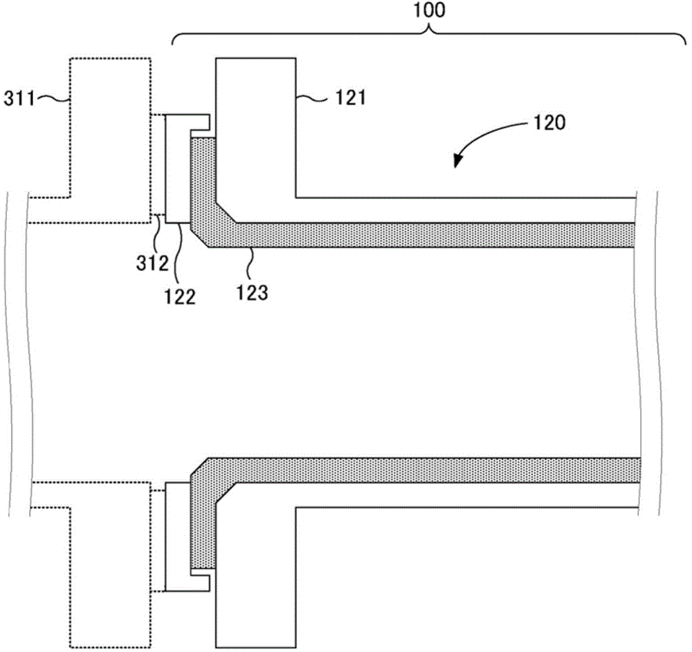
[0055] Exemplary embodiments of the present invention will be described with reference to the drawings. figure 1 is a cross-sectional view of a coupling portion between the flange portion 121 of the measuring tube 120 and the pipe-side flange portion 311 of the electromagnetic flowmeter 100 according to the first exemplary embodiment of the present invention. At the same time, the coupling structure between the electromagnetic flowmeter 100 and the pipeline can be Figure 13 The prior art coupling structure shown is the same.
[0056] Such as figure 1 As shown, the lining material 123 is bonded or welded to the inner side of the measuring tube 120 of the electromagnetic flowmeter 100 (a part of the region including the coupling side of the flange portion 121 ). When the electromagnetic flowmeter side flange part 121 and the pipe side flange part 311 are coupled together, the electromagnetic flowmeter side flange part 121 and the pipe side flange part 311 are fastened togeth...
PUM
 Abstract
Description
Claims
Application Information