

Heat-transfer tube with groove on inwall and method for manufacturing heat exchanger using the heat-transfer tube
A manufacturing method and heat exchanger technology, applied in heat exchange equipment, tubular elements, lighting and heating equipment, etc., can solve the problems of reduced condensation performance, insufficient performance, difficult condensation performance, etc., and achieve the effect of suppressing deformation
- Summary
- Abstract
- Description
- Claims
- Application Information
AI Technical Summary
Problems solved by technology
Method used
Image

Examples
Embodiment 1
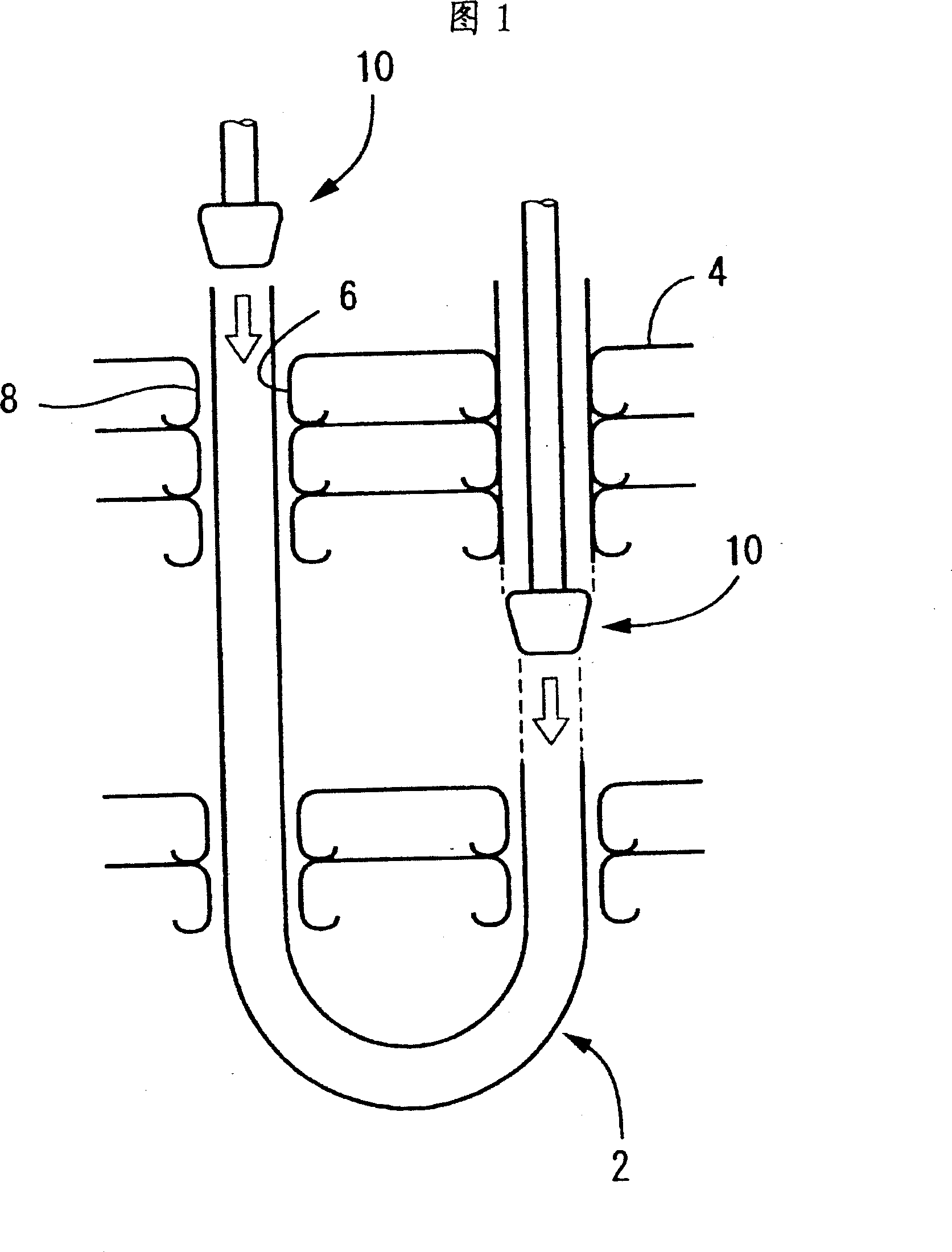
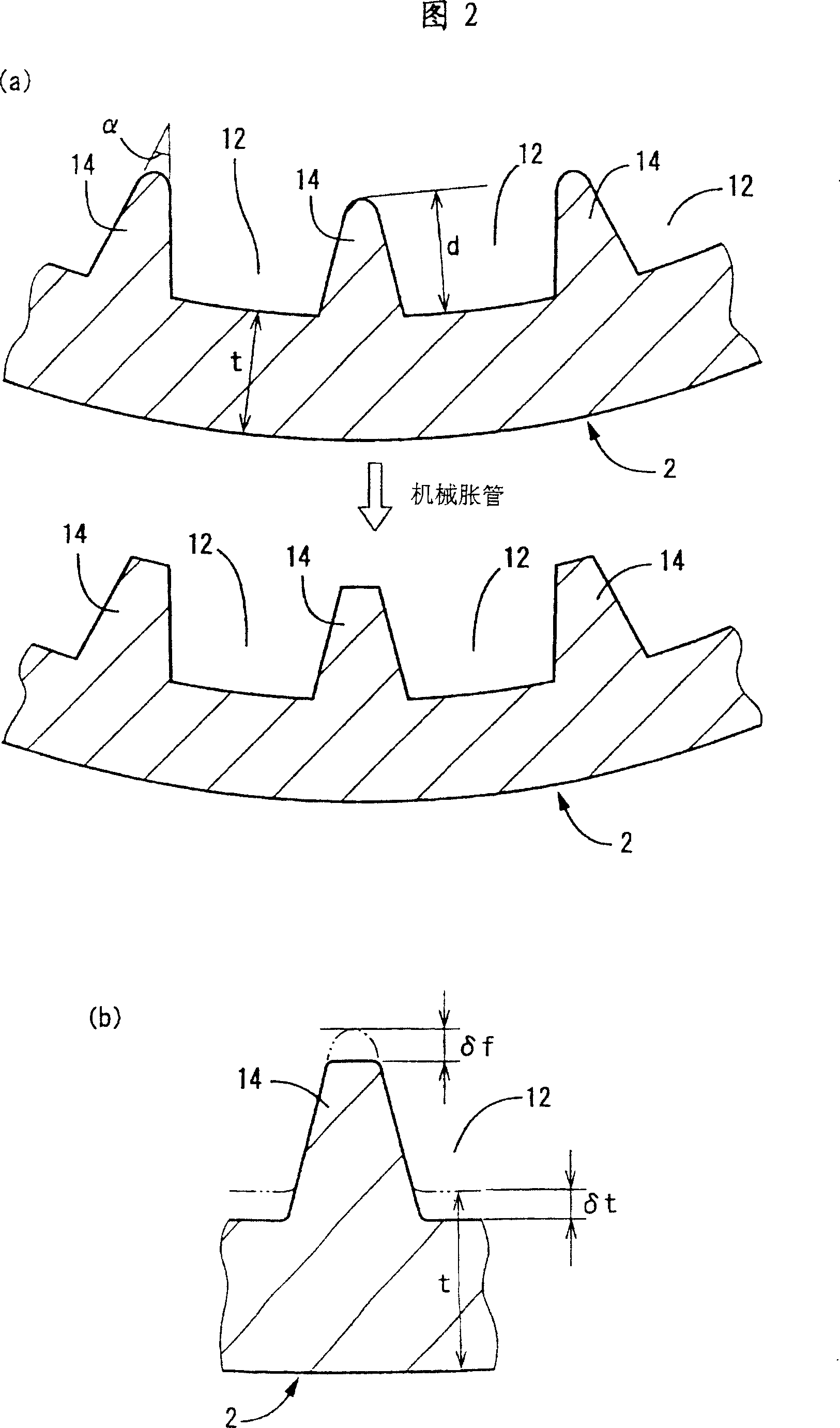
[0035] First, the outer diameter of the tube is 4-10mm, the depth (d) of the groove is 0.1-0.3mm, the helix angle of the groove is 10-30°, the fin top angle (α) is 20-40°, and the number of grooves is 30 In the range of ~80, through the same copper tube rolling process as in the past, various tubes (2) with spiral grooves on the inner wall were trial-manufactured, and then mechanically expanded at a tube expansion rate of 4 to 7% as in Figure 1. Tubes, assemble the tubes (2) into the aluminum fins (4) to make heat exchangers respectively.
[0036] Next, the aluminum fins (4) were removed from the obtained heat exchanger, and the tubes (2) with inner spiral grooves after tube expansion were sampled to investigate the base wall thickness of each. As a result, it can be found that for tubes whose base wall thickness (t) is reduced by 8 μm or more after tube expansion compared with the base wall thickness (t) before tube expansion, fin deformation such as fin destruction or fin lo...
Embodiment 2
[0039] As in Example 1, a tube with a spiral groove on the inner wall with an outer diameter between 6 and 9.52 mm was trial-produced by rolling a copper tube, and the base wall thickness (t) was changed, and two rows of 8 tubes were further produced by mechanical expansion. segment heat exchanger. Utilize in Fig. 2 the reduction (δ f ) and the reduction of base wall thickness (δ t ), to detect the decrease in fin height after tube expansion (δ f ) and the reduction of base wall thickness (δ t ), record the results and the dimensions of the trial-manufactured tubes before expansion into the table below:
[0040] Example of the invention
[0041] As can be seen from the results in Table 1, each of the trial pipes related to Examples 1 to 4 of the present invention is due to the base wall thickness reduction (δ t ) is above 8μm, so the fin after tube expansion is destroyed (δ f ) is less than 9 μm, therefore, it can be considered that the effect of sufficiently ...
Embodiment 3
[0043] In order to confirm the influence of the effect of preventing fin deformation during tube expansion on the performance of the heat exchanger, using the trial tubes of Example 4 of the present invention and Comparative Example 6 shown in Table 1 above, the individual heat exchangers produced separately were tested. performance evaluation. That is, using the measurement conditions shown in Table 2 below, in the case of circulating the cooling medium as shown in Figure 4 or Figure 5, an evaporation test or a condensation test that reflects the performance of the heat exchanger as a single unit is implemented according to a known method, and the investigation is carried out. The evaporation capacity (cooling capacity) and condensation capacity (warming capacity) in each heat exchanger unit are shown in Fig. 6 and Fig. 7 respectively as heat exchange capacity-front wind speed curves.
[0044] test
evaporate
condensation
air side
dry bulb temperatu...
PUM
 Abstract
Description
Claims
Application Information