Camera tracking method and device

A camera and image technology, applied in the field of computer vision, can solve problems such as difficult to eliminate and estimation errors

Inactive Publication Date: 2015-09-16
HUAWEI TECH CO LTD
View PDF4 Cites 36 Cited by
  • Summary
  • Abstract
  • Description
  • Claims
  • Application Information

AI Technical Summary

Problems solved by technology

[0003] In practical applications, PTAM and ACTS systems perform camera tracking for monocular video sequences. During the camera tracking process, two frames need to be selected as initial frames. figure 1 It is a schematic diagram of camera tracking based on monocular video sequences in the prior art, such as figure 1 As shown, using the matching points of the initial frame 1 image and the initial frame 2 image (x 1,1 ,x 1,2 ) to estimate the relative position between the corresponding cameras of the two initial frame images (R 12 ,t 12 ); Initialize matching points by triangulation (x 1,1 ,x 1,2 ) corresponds to scene po...

Method used


Image

  • Camera tracking method and device
  • Camera tracking method and device
  • Camera tracking method and device

Examples


Embodiment 1

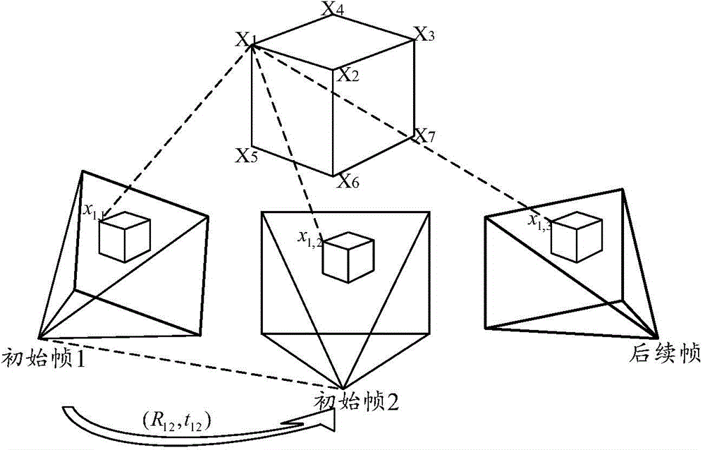
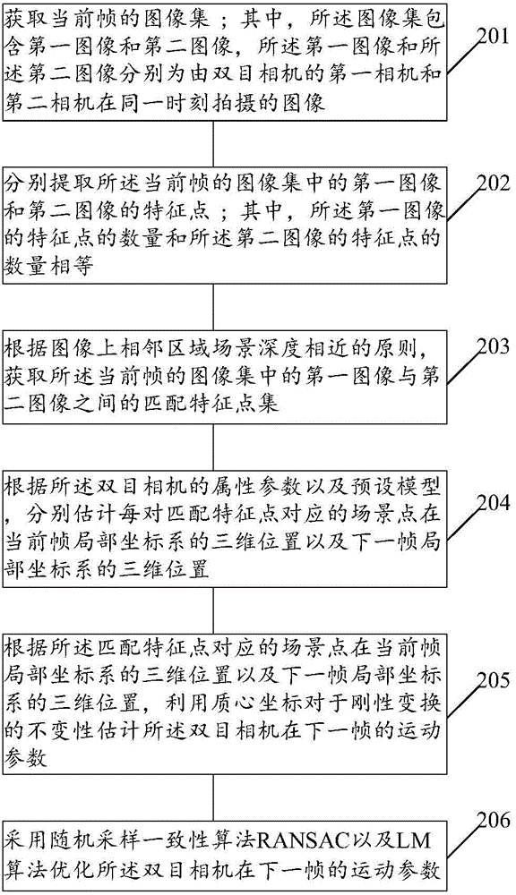
[0149] figure 1 A flow chart of a camera tracking method provided by an embodiment of the present invention, such as figure 2 As shown, the following steps may be included:

[0150]201: Obtain the image set of the current frame; wherein, the image set includes a first image and a second image, and the first image and the second image are respectively obtained by the first camera and the second camera of the binocular camera Images taken at the same time.

[0151] Wherein, the image set of the current frame belongs to the video sequence taken by the binocular camera; the video sequence is a collection of image sets taken by the binocular camera within a period of time.

[0152] 202: Extract respectively feature points of the first image and the second image in the image set of the current frame; wherein, the number of feature points of the first image is equal to the number of feature points of the second image.

[0153] Wherein, the feature points usually refer to the poin...

Embodiment 2

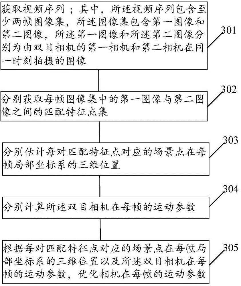
[0221] image 3 A flowchart of a camera tracking method provided by an embodiment of the present invention, such as image 3 As shown, the following steps may be included:

[0222] 301: Acquire a video sequence; wherein, the video sequence includes at least two frame image sets, the image set includes a first image and a second image, and the first image and the second image are respectively captured by a binocular camera Images captured by the first camera and the second camera at the same moment.

[0223] 302: Acquire matching feature point sets between the first image and the second image in each frame image set.

[0224] It should be noted that the method of obtaining the matching feature point set between the first image and the second image in each frame image set is the same as the method of obtaining the matching feature point set between the first image and the second image in the current frame image set in Embodiment 1. The method of point set is the same and will...

Embodiment 3

[0233] Figure 4 A structural diagram of a camera tracking device 40 provided for an embodiment of the present invention, as shown in Figure 4 shown, including:

[0234] The first acquisition module 401: used to acquire the image set of the current frame; wherein, the image set includes a first image and a second image, and the first image and the second image are the first images of the binocular camera respectively. The image captured by the camera and the second camera at the same moment.

[0235] Wherein, the image set of the current frame belongs to the video sequence shot by the binocular camera; the video sequence is a collection of image sets shot by the binocular camera within a period of time.

[0236] Extraction module 402: for extracting feature points of the first image and the second image in the image set of the current frame acquired by the first acquisition module 401 respectively; wherein, the number of feature points of the first image and the number of f...


PUM


Abstract

Provided are a camera tracking method and device, which use a binocular video image to perform camera tracking, thereby improving the tracking accuracy. The camera tracking method provided in the embodiments of the present invention comprises: acquiring an image set of a current frame; respectively extracting feature points of each image in the image set of the current frame; according to a principle that depths of scene in adjacent regions on an image are similar, acquiring a matched feature point set of the image set of the current frame; according to an attribute parameter and a pre-set model of a binocular camera, respectively estimating three-dimensional positions of scene points corresponding to each pair of matched feature points in a local coordinate system of the current frame and a local coordinate system of the next frame; and according to the three-dimensional positions of the scene points corresponding to the matched feature points in the local coordinate system of the current frame and the local coordinate system of the next frame, estimating a motion parameter of the binocular camera in the next frame using the invariance of a barycentric coordinate with respect to rigid transformation, and optimizing the motion parameter of the binocular camera in the next frame.

Description

technical field [0001] The invention relates to the field of computer vision, in particular to a camera tracking method and device. Background technique [0002] Camera tracking (Camera tracking) is one of the most basic problems in the field of computer vision. According to the video sequence shot by the camera, the three-dimensional position of the feature point in the shooting scene and the camera motion parameters corresponding to each frame of image are estimated; with the rapid development of technology With the progress, the application fields of camera tracking technology are very extensive, such as robot navigation, intelligent positioning, combination of virtual reality, augmented reality, three-dimensional scene browsing, etc.; in order to adapt to the application of camera tracking in various fields, after decades of hard research, some cameras Tracking systems have also been launched, such as PTAM (Parallel Tracking and Mapping), ACTS (Automatic Camera Tracking ...

Claims


Application Information

Patent Timeline
IPC IPC(8): G06T7/20
CPCG01C11/06G06T2207/10021G06T7/246G06T7/579G06T2207/30244G06V20/64G06V20/10G06T7/73
Inventor 鲁亚东章国锋鲍虎军
Owner HUAWEI TECH CO LTD
Why Eureka
Try Eureka