Three-dimensional digital particle image generation device and method based on excitation adsorption

An image generation device, three-dimensional digital technology, applied in the direction of measuring device, particle and sedimentation analysis, particle size analysis, etc., can solve the problems that affect surface data acquisition, synthesis, processing, analysis, high cost, difficult application, etc., and achieve uniform and clear results Size, effect of achieving stability

Active Publication Date: 2018-04-10
GUANGZHOU MECHANICAL ENG RES INST
View PDF10 Cites 0 Cited by
  • Summary
  • Abstract
  • Description
  • Claims
  • Application Information

AI Technical Summary

Problems solved by technology

Although these devices have improved the accuracy of measurement, their cost is high, and they are difficult to apply in fault diagnosis engineering. They are limited by the observation environment and related accessories, which affects the collection of surface data and subsequent synthesis processing. ,analyze

Method used


Image

  • Three-dimensional digital particle image generation device and method based on excitation adsorption
  • Three-dimensional digital particle image generation device and method based on excitation adsorption
  • Three-dimensional digital particle image generation device and method based on excitation adsorption

Examples


Embodiment 1

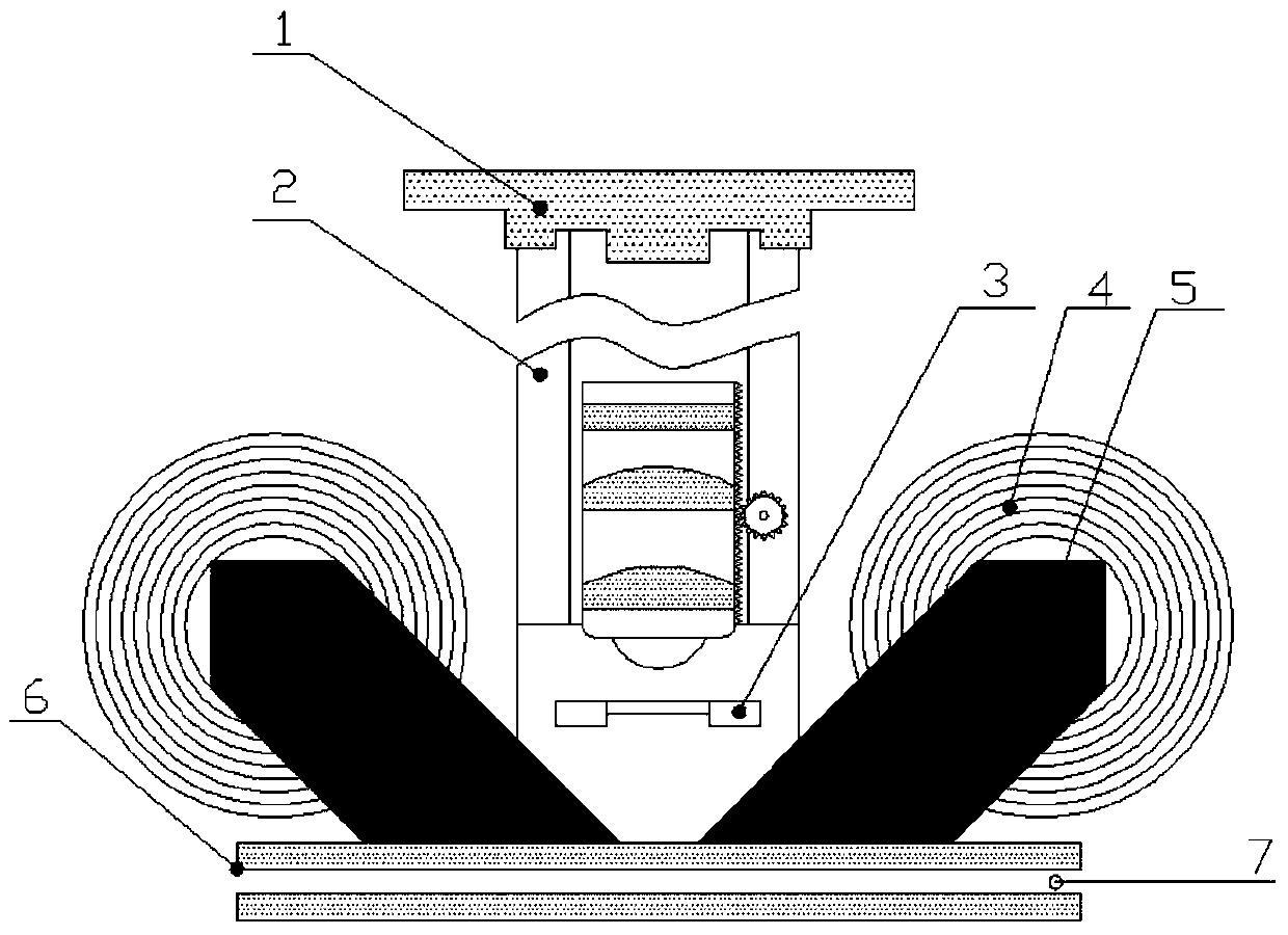
[0032] figure 1 An embodiment of the present invention is illustrated, including an imaging module, an adsorption module, a picture processing module and a light-transmitting sheet 6, and the picture processing module is connected to the imaging module. The imaging module includes an imaging device 1, an optical filter, a lens group, a focusing mechanism 2 and a reflective light source 3. The imaging device 1, the optical filter and the lens group are connected in sequence, the optical filter is arranged above the lens group, and the imaging device 1 is located at Above the filter, the focusing mechanism 2 is arranged on the lens group, and the reflective light source 3 is located below the lens group. The lens group includes one or more lenses to magnify the particle image, and the filter to filter the color. The adsorption module includes an iron core frame, an adsorption component 5 and an inductance coil 4 wound on the iron core frame.

[0033] The imaging module and the...

Embodiment 2

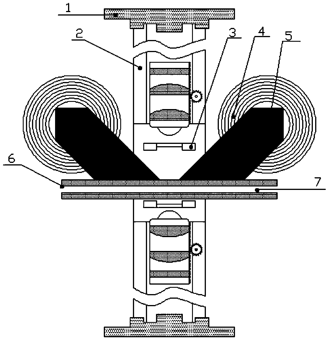
[0047] attached figure 2 Another embodiment of the present invention is illustrated, with the accompanying figure 1 Compared with the illustrated embodiment, a group of imaging modules and light-transmitting sheets are mainly added. The added group of imaging modules and light-transmitting sheets is the same as the group of imaging modules and light-transmitting sheets in Embodiment 1, with the flow channel 7 as the axis of symmetry, symmetrical up and down; the imaging module is the same as the embodiment, and also includes imaging devices 1. Focusing mechanism 2, lens group, reflected light source 3 and optical filter.

[0048] In this embodiment, the focusing mechanism 2 located above and below the flow channel 7 can be adjusted simultaneously. The central position between the two groups of adsorption components 5 is on the same optical path as the center of the reflective light source 3, the focusing mechanism 2, and the imaging device 1; the center of the optical path ...


PUM

PropertyMeasurementUnit
transmittivityaaaaaaaaaa

Abstract

The invention discloses a three-dimensional digital particle image generation device and method based on excitation adsorption. In the device, the imaging module and the adsorption module are arranged on the same side of the light-transmitting sheet, the light-transmitting sheet is arranged on the upper surface of the flow channel, and the light-transmitting sheet is located on the imaging module. In the center of the optical path and the magnetic field generated after the adsorption module is powered on, the adsorption module adsorbs the particles to the bottom of the light-transmitting sheet; the imaging module is equipped with a focusing mechanism for adjusting the focal length to obtain images of different focal planes; Different differential operators and wavelet image processing are used to divide the focal plane range, and the morphological processing method is used to measure the three-dimensional surface of magnetic particles, and through Boolean algebra operations, different focal plane images are superimposed and reconstructed into a new particle image. The invention adsorbs particles on the same plane through an adsorption module, obtains images of different focal planes for synthesis processing, and generates clear and stable three-dimensional digital particle images.

Description

technical field [0001] The invention relates to a technology for analyzing and judging the operating state of mechanical equipment by detecting magnetic particles in a fluid, in particular to a three-dimensional digital particle image generation device and method based on excitation adsorption. Background technique [0002] Generally speaking, the commonly used technology for online monitoring and analysis to judge the lubrication and wear state of equipment is ferrographic oil monitoring technology. Ferrographic oil monitoring technology appeared in the 1970s. Through the deposition and analysis of ferromagnetic particles in the lubricating oil in use, the operating status and wear trend of the equipment are monitored, the wear mechanism is judged, and the early failure prevention of the equipment is realized and the failure is reduced. It has the advantages of stable performance, reliability, and strong anti-interference ability. [0003] Ferrography oil monitoring techno...

Claims


Application Information

Patent Timeline
Patent Type & Authority Patents(China)
IPC IPC(8): G01N15/02
Inventor 陈闽杰贺石中冯伟冼建波何佳乐陶辉
Owner GUANGZHOU MECHANICAL ENG RES INST
Why Eureka
Try Eureka