Constant-voltage constant-current LED bulb light driver

An LED bulb lamp, constant voltage and constant current technology, which is applied in the direction of electric lamp circuit arrangement, lighting device, light source, etc., can solve the problems of complex circuit structure, power loss, high failure rate, etc., to improve the power saving rate and simple structure. Effect

Inactive Publication Date: 2015-10-28
黄鹂
View PDF5 Cites 0 Cited by
  • Summary
  • Abstract
  • Description
  • Claims
  • Application Information

AI Technical Summary

Problems solved by technology

[0002] The current LED bulb lamps all use RC step-down or pulse constant current driving power. The problem with these driving power is that the circuit structure is complicated, and the electronic components used are many, causing a high failure rate; and the driver uses many power consumption. Energy-saving resistor elements consume a certain amount of electric energy, reducing the energy-saving rate of LED bulbs

Method used


Image

  • Constant-voltage constant-current LED bulb light driver

Examples


Embodiment Construction

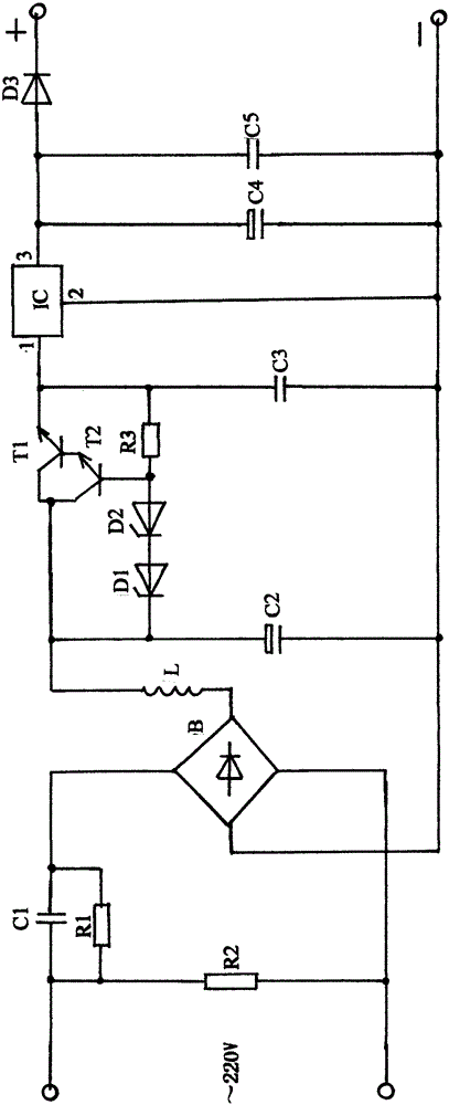
[0006] As shown in the figure, R1 and C1 are resistance-capacitance step-down circuits, and C1 is a polyester capacitor with a withstand voltage of more than 400V. R1 is a bleeder resistor with a large resistance and low power. The resistance-capacitance step-down circuit has the function of constant current power supply, and supplies the LED working power with constant current. B is a single-phase bridge rectifier, which converts the reduced alternating current into a pulsating direct current. Inductor L and capacitor C2 form a composite filter circuit. One function is to turn the pulsating DC power into a relatively smooth DC power and send it to the next stage circuit; The power factor of the light bulb.

[0007] As shown in the attached picture, IC and peripheral circuits form a high-voltage input three-terminal voltage regulator circuit, in which R3, D1, D2, T1, T2 form a series step-down circuit. When D1 and D2 use a double-terminal voltage regulator, the voltage is 12...


PUM


Abstract

The invention relates to a constant-voltage constant-current LED bulb light driver. A constant current characteristic of a capacitance-resistance voltage reduction circuit is used for providing constant currents for the LED; and a high-input-voltage three-end input circuit is used for providing constant output voltages for the LED. Therefore, the LED bulb light has the constant-voltage constant-current operating characteristic, thereby guaranteeing the durability of the LED bulb light.

Description

technical field [0001] The invention relates to a constant voltage and constant current LED bulb lamp driver. Background technique [0002] The current LED bulbs are driven by resistance-capacitance step-down or pulse constant current. The problem of these driving power sources is that the circuit structure is complex, the electronic components used are many, and the failure rate is high; the driver uses a lot of power consumption. The energy-saving resistance element consumes a certain amount of electric energy, which reduces the energy saving rate of the LED bulb. SUMMARY OF THE INVENTION [0003] The present invention is a constant voltage and constant current LED bulb lamp driver, and discloses an LED bulb lamp driver with constant voltage and constant current power supply function. The small electronic components make the electric energy absorbed by the lamp from the power source converted into light energy to the maximum extent, which improves the power saving rate ...

Claims


Application Information

Patent Timeline
IPC IPC(8): H05B37/02
Inventor 黄鹂
Owner 黄鹂
Why Eureka
Try Eureka