A kind of rolling piston for refrigeration compressor and its manufacturing method

A refrigeration compressor, rolling piston technology, applied in rotary piston/swing piston pump components, machines/engines, rotary piston pumps, etc., can solve the problems affecting the health of operators, complex manufacturing process and poor working environment and other problems, to achieve the effect of good processability, cost saving and low friction resistance

A refrigeration compressor, rolling piston technology, applied in rotary piston/swing piston pump components, machines/engines, rotary piston pumps, etc., can solve the problems affecting the health of operators, complex manufacturing process and poor working environment and other problems, to achieve the effect of good processability, cost saving and low friction resistance

CN105041658BActive Publication Date: 2018-06-12NINGBO YONGWEI GROUP

Image

  • A kind of rolling piston for refrigeration compressor and its manufacturing method

Examples


Embodiment Construction

[0028] The present invention will be further described in detail below in conjunction with the accompanying drawings and embodiments.

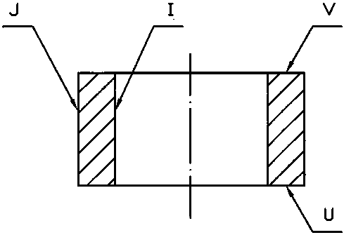
[0029] A rolling piston for a rotary refrigeration compressor, the piston material is a steel pipe after carburizing steel cold rolling.

[0030] The material of the rolling piston is steel pipe after carburizing steel cold rolling.

[0031] In this embodiment, the chemical composition of the carburized steel is as follows in % by weight: C0.17-0.23 Si0.17-0.37 Mn0.90-1.20 Cr0.90-1.20 Fe balance. Specifically: 20CrMn.

[0032] In another embodiment, the chemical composition of the above carburized steel is as follows by weight: C0.17-0.23 Si0.17-0.37 Mn0.80-1.10 Cr1.00-1.30 Ti 0.04-0.10 Fe balance. Specifically: 20CrMnTi.

[0033] A method for manufacturing a rolling piston for a rotary refrigeration compressor, comprising the steps of:

[0034] (1) Select carburized steel and cold roll it into a steel pipe that meets the precision require...


PUM

PropertyMeasurementUnit
hardnessaaaaaaaaaa

Abstract

Provided is a rolling piston for a rotary type refrigeration compressor. The rolling piston is made of a steel tube which is formed by conducting cold-rolling on carburizing steel. Chemical components of the carburizing steel include 0.17%-0.23% of C, 0.17%-0.37% of Si, 0.80%-1.10% of Mn, 1.00%-1.30% of Cr, 0.04%-0.10% of Ti and the balance Fe. The rolling piston has the advantages that the supply of goods is ample, the price is low, the cost is reduced, and the environment is not polluted.

Description

technical field [0001] The invention relates to a refrigeration compressor component and a manufacturing method thereof. Background technique [0002] Rotary refrigeration compressors, also known as rolling rotor compressors, use piston rotation to compress refrigerant gas. It has been on the market for many years, and it is one of the most commonly used compressors at present. [0003] The rolling piston is an important part of the rotary refrigeration compressor sleeve. It is set on the eccentric turn of the eccentric shaft of the compressor. It rolls along the cylinder wall during refrigeration. Contact, forming a dynamic seal, with the use of new environmentally friendly refrigerants, high efficiency, and energy saving in rotary compressors becoming more and more diversified, a more advanced proposal is made for rolling pistons that can be applied to severe conditions such as high load, high power, high temperature, and high pressure. high demands. [0004] For a long ...

Claims


Application Information

Patent Timeline
12 Jun 2018
Publication
CN105041658B
IPC
F04C29/00; F04C18/356; B23P15/10
Inventors
庄希平; 夏祖伟