Automatic emergency light system based on surge current limiting

A surge current and emergency light technology, applied in the field of circuits, can solve the problems of reduced sensitivity of the system circuit, unable to enter the working state in time, easy to damage, etc., so as to improve the excessive current, avoid high current damage, and avoid waste of electric energy. Effect

Inactive Publication Date: 2015-11-11
CHENGDU JIESHENG TECH CO LTD
View PDF0 Cites 1 Cited by
  • Summary
  • Abstract
  • Description
  • Claims
  • Application Information

AI Technical Summary

Problems solved by technology

[0003] The purpose of the present invention is to overcome the defects that the existing emergency lights are easy to be damaged because the current of the system circuit is too large or too small to reduce the induction sensitivity and cannot enter the working state in time when the power is suddenly cut off. Automatic emergency light system with inrush current limitation

Method used


Image

  • Automatic emergency light system based on surge current limiting
  • Automatic emergency light system based on surge current limiting
  • Automatic emergency light system based on surge current limiting

Examples


Embodiment

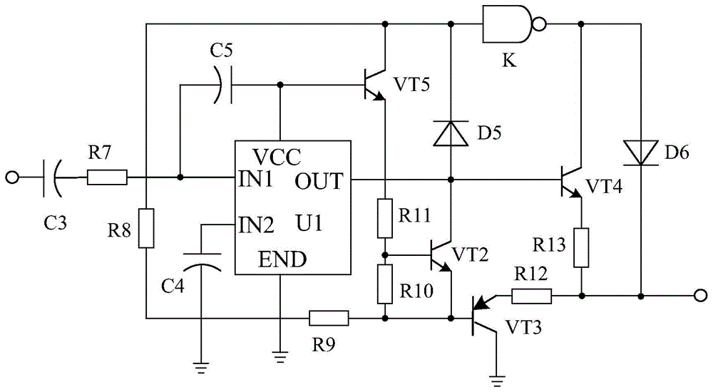
[0021] Such as figure 1 As shown, the present invention mainly consists of an emergency light XL, a battery GB, a light control circuit connected to the positive and negative poles of the battery GB, a switch circuit connected to the output end of the light control circuit, and a delay circuit connected to the output end of the switch circuit , an amplifier circuit connected to the output end of the delay circuit, a linear drive circuit and a surge current limiting circuit arranged between the light control circuit and the switch circuit. The emergency light XL is connected with the amplifying circuit.

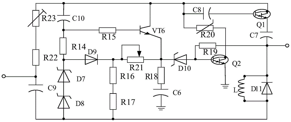
[0022] The structure of the inrush current limiting circuit is as image 3 As shown, it consists of PDP type Linton tube Q1, PDP type Linton tube Q2, triode VT6, inductor L, resistor R14, resistor R15, resistor R16, resistor R17, resistor R18, resistor R19, thermistor R20, resistor R21, Resistor R22, resistor R23, polarized capacitor C6, polarized capacitor C7, polarized cap...


PUM


Abstract

The invention discloses an automatic emergency lamp system sensitive in induction. The automatic emergency lamp system comprises an emergency lamp XL, a battery GB, a light control circuit connected with the positive pole and the negative pole of the battery GB, a switching circuit connected with the output terminal of the light control circuit, a time delay circuit connected with the output terminal of the switching circuit, and an amplifying circuit connected with the output terminal of the time delay circuit, wherein the emergency lamp XL is connected with the amplifying circuit. The automatic emergency lamp system is characterized by also comprising a linear driving circuit connected between the light control circuit and the switching circuit, wherein the linear driving circuit comprises a driving chip U1, an audion VT2, an audion VT3, an audion VT4, an audion VT5, a polar capacitor C3 and the like; the positive pole of the polar capacitor C3 is connected with the light control circuit and the negative pole of the polar capacitor C3 passes through a resistor R7 and then is connected with an IN1 pin of a driving chip U. The automatic emergency lamp system is provided with the linear driving circuit, and can improve the sensitivity of the emergency lamp.

Description

technical field [0001] The invention relates to a circuit, in particular to an automatic emergency light system based on surge current limitation. Background technique [0002] As people's requirements for quality of life are getting higher and higher, lighting is becoming more and more important in people's production and life. At present, lighting lamps have been widely used in people's lives, which has brought great convenience to people. However, it is inevitable to encounter situations such as sudden power failure or fuse blown in daily life. At this time, the darkness in the room has brought great troubles to people's normal activities. At present, there are different kinds of emergency lights on the market. However, when the current of the existing emergency lights is suddenly cut off, the current of the system circuit is too large, so that the induction sensitivity is reduced and cannot enter the working state in time, and even cause its damage. People's normal act...

Claims


Application Information

Patent Timeline
Patent Type & Authority Applications(China)
IPC IPC(8): H05B37/02
CPCY02B20/40
Inventor 雷明方
Owner CHENGDU JIESHENG TECH CO LTD
Why Eureka
Try Eureka