Micro channel heat exchanger for heat pump air conditioner

A technology of micro-channel heat exchanger and heat pump air conditioner, which is applied in the direction of heat exchanger shell, heat exchange equipment, evaporator/condenser, etc., can solve problems that affect product function, reduce heat exchange efficiency of heat exchanger, and produce quality problems and other problems, to achieve the effect of reasonable product structure, simple and feasible processing, and small wind resistance

Inactive Publication Date: 2015-12-09
浙江康盛热交换器有限公司
View PDF6 Cites 5 Cited by
  • Summary
  • Abstract
  • Description
  • Claims
  • Application Information

AI Technical Summary

Problems solved by technology

For example, in winter heating conditions, due to the temperature difference between the external environment and the cooling medium flowing through the flat tube, a dew liquid film will be formed on the surface of the flat tube, so that water droplets will also form in the middle of the heat sink. If the dew is not discharged from the surface of the flat tube and heat sink in time, and the ambient temperature is very low, frosting will occur on the surface of the flat tube in a short period of time, and the increase of the frosting area will reduce the overall performance of the heat exchanger. Heat transfer efficiency
[0005] At present, the heat pump air conditioner has an intelligent defrosting function. During the defrosting cycle, due to the structural design defect of the previous parallel flow heat exchanger, the dew on the surface of the flat tube cannot be eliminated. After many tests and observations, the first defrosting stage was completed Return to the normal heating condition, and the frosting phenomenon on the surface of the flat tube will be regenerated in less than 5 minutes. This phenomenon will not only affect the product function but also cause problems in product quality.

Method used


Image

  • Micro channel heat exchanger for heat pump air conditioner
  • Micro channel heat exchanger for heat pump air conditioner

Examples


Embodiment Construction

[0015] The present invention will be further described below in conjunction with accompanying drawing and specific embodiment:

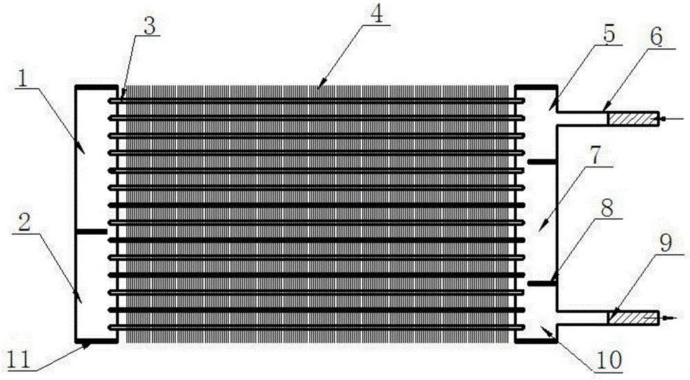
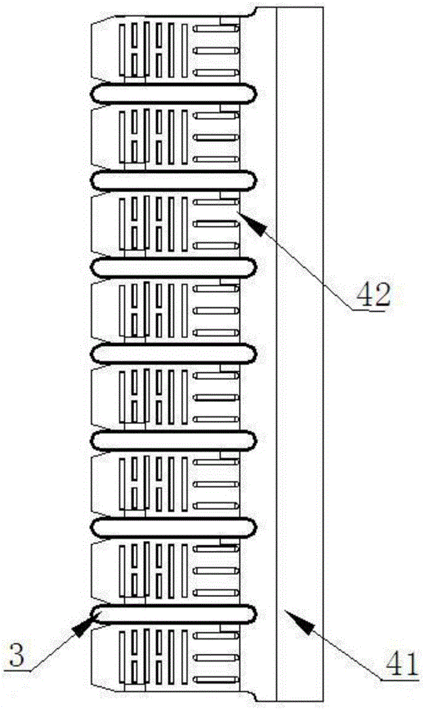
[0016] Such as figure 1 and figure 2 As shown, a microchannel heat exchanger for a heat pump air conditioner includes a vertically arranged hollow first header and a second header, and is horizontally spaced between the first header and the second header And several flat tubes 3 communicated with the first header and the second header, as well as being arranged at both ends of the first header and the second header and sealing the first header and the second header The end cover 11 of the first collecting pipe is connected with the inlet pipe 6 at the upper end of the first collecting pipe, and the outlet pipe 9 is connected with the lower end of the first collecting pipe, and also includes a plurality of fins 4 at intervals in parallel, and each fin 4 is arranged perpendicular to the flat pipe 3, Each fin 4 includes a plurality of heat dissipatio...


PUM


Abstract

The invention discloses a micro channel heat exchanger for a heat pump air conditioner. The micro channel heat exchanger comprises a hollow first collecting tube and a hollow second collecting tube which are vertically arranged, a plurality of flat tubes which are horizontally spaced between the first collecting tube and the second collecting tube and communicate with the first collecting tube and the second collecting tube, and end covers which are arranged at the two ends of each of the first collecting tube and the second collecting tube for sealing the first collecting tube and the second collecting tube, wherein the upper end of the first collecting tube communicates with an inlet tube; the lower end of the first collecting tube communicates with an outlet tube; a micro channel for allowing a refrigerant to flow is arranged in the flat tubes; and a flow-splitting spacer for blocking the refrigerant is arranged in the first collecting tube and the second collecting tube. The micro channel heat exchanger for the heat pump air conditioner is small in air resistance, and capable of smoothly discharging condensed water formed on the surface of the heat exchanger and improving the heat exchange efficiency; and the heat exchanger product is reasonable in structure, and is simple and feasible to process.

Description

Technical field: [0001] The invention relates to a microchannel heat exchanger, in particular to a microchannel heat exchanger for a heat pump air conditioner. Background technique: [0002] The heat pump air conditioning system consists of a compressor, a condenser, an evaporator, a throttling device, and a four-way valve. The condenser and the evaporator are the heat exchange components of the heat pump air conditioning system, collectively referred to as heat exchangers. With the continuous development of technology, the application of parallel flow heat exchangers has been widely used in cooling-only air conditioners. Parallel flow heat exchangers generally use aluminum as the main body, including a header, an inlet pipe and an outlet pipe arranged on the header, a number of flat tubes connected to the header and the inner cavity of the header and The cooling fins are arranged between adjacent flat tubes, the flat tubes are arranged parallel to each other and spaced apa...

Claims


Application Information

Patent Timeline
IPC IPC(8): F25B39/00F28F1/32F28F9/02F28F17/00F28F21/08
Inventor 周景春兰兆忠黄锋马亚玲朱丽星滑翔
Owner 浙江康盛热交换器有限公司
Why Eureka
Try Eureka