An implantable medical detector

An implantable medical and detector technology, used in sensors, medical science, diagnostic recording/measurement, etc., can solve the problems of narrow antenna frequency range, affecting communication quality, limited space size, etc., and achieve wide antenna frequency range and high gain. , the effect of reasonable structure

Inactive Publication Date: 2016-06-08
NORTH CHINA UNIVERSITY OF SCIENCE AND TECHNOLOGY
View PDF5 Cites 0 Cited by
  • Summary
  • Abstract
  • Description
  • Claims
  • Application Information

AI Technical Summary

Problems solved by technology

However, implantable medical diagnostic devices have certain problems, including battery life, materials, etc., but one of the biggest problems is the quality of communication. Due to the limited space of implantable medical diagnostic devices, they are often placed in The antennas in it all have shortcomings such as narrow frequency range, poor isolation, and low gain, which seriously affect the quality of communication and thus the quality of diagnosis.

Method used


Image

  • An implantable medical detector
  • An implantable medical detector
  • An implantable medical detector

Examples


Embodiment 1

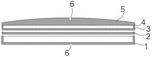
[0033] like Figure 1 to Figure 8 As shown, an implantable medical detector described in this embodiment includes an implantable electronic medical unit, and also includes a disc-shaped bottom case 1, and the bottom case 1 is provided with a device for accommodating the implantable electronic medical unit. The accommodation chamber of the unit; it also includes a spacer 2 covering the opening of the bottom case 1; the spacer 2 is provided with a disc-shaped middle case 3 for placing the antenna; it also includes a cover case 5 for covering the opening of the middle case 3 ; The middle shell 3 is provided with a communication antenna for allowing the implantable electronic medical unit to communicate with the outside world. In the implantable medical detector described in this embodiment, the top of the cover shell 5 is an arc surface. The present invention provides a better installation module for the research and development of implantable medical diagnostic devices, and eac...

Embodiment 2

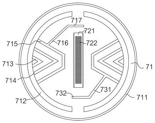
[0037] The difference between the implantable medical detector described in this embodiment and Embodiment 1 is that specific optimal parameters are set, so that the antenna structure is more stable, and the communication performance is more reliable and stable without jumping; specifically, the The angle of the angle near the center of the second radiation arm 713 is the same as the angle of the angle of the third radiation arm 714 near the center, and both are greater than 15° and less than 60°. In the implantable medical detector described in this embodiment, the distance between the rectangular notches 722 is set as M; the number of the rectangular notches 722 is set as N; the lengths of the second parasitic oscillator arm 717 and the fourth parasitic oscillator arm 732 are set The same and the length is set as K; the K=M*0.25*N; the unit of M and K is millimeter. After setting the above parameter limits, it is found through a large number of experiments and simulations th...


PUM


Abstract

Disclosed in the invention is an implantable medical detector comprising an implantable electronic medical unit, a plate-shaped bottom shell, an isolation plate, and a cover shell. An accommodation cavity for accommodating the implantable electronic medical unit is arranged in the bottom shell; the isolation plate covers an opening of the bottom shell and is provided with a plate-shaped middle shell for placing an antenna; and the cover shell covers an opening of the middle shell. Besides, a communication antenna for realizing communication between the implantable electronic medical unit and an external world is arranged in the middle shell. The structure is reasonable; no pricking feeling on the human body is caused; the internal structure is designed reasonably; and the antenna arranged in the detector has a wide frequency range, good isolation, and a high gain. A good installation module is provided for development of an implantable medical diagnosis device. As long as enterprises design respective implantable electronic medical units into ones that have shapes and thicknesses or sizes and can be placed in the bottom shell, the good communication quality can be realized.

Description

technical field [0001] The present invention relates to an implantable medical detector. Background technique [0002] At present, there are many types of implanted medical devices, such as implanted cardiac pacemakers, brain pacemakers, nerve stimulators, muscle stimulators, ECG recorders, etc., and now there are diagnostic devices implanted in the human body. For real-time diagnosis of patient's heartbeat, pulsation, blood pressure or other information, like other implantable medical devices, it still needs to communicate with the outside world in order to transmit the information in real time. At present, the diagnostic device generally consists of a uniquely designed small device box and an implanted electronic medical unit in the device box; plus an antenna for connecting the implanted electronic medical unit to the outside world, the implanted electronic medical unit generally Contains detection circuit, detector, battery, etc. However, implantable medical diagnostic...

Claims


Application Information

Patent Timeline
Patent Type & Authority Patents(China)
IPC IPC(8): H01Q1/38H01Q1/22H01Q1/52A61B5/00
Inventor 刘志友高峰魏韬徐强张胜江健良
Owner NORTH CHINA UNIVERSITY OF SCIENCE AND TECHNOLOGY
Why Eureka
Try Eureka