Unit magnetic pole structure of permanent magnet motor rotor

A permanent magnet motor, magnetic pole structure technology, applied in the magnetic circuit shape/style/structure, magnetic circuit rotating parts, manufacturing stator/rotor body and other directions, can solve problems such as complex situations, achieve convenient operation, and enhance axial positioning and sealing, preventing tooth rise

Active Publication Date: 2016-01-13
愿景动力有限公司
View PDF7 Cites 5 Cited by
  • Summary
  • Abstract
  • Description
  • Claims
  • Application Information

AI Technical Summary

Problems solved by technology

[0003] For permanent magnet motors with radial ventilation trenches, the situation is more complicated

Method used


Image

  • Unit magnetic pole structure of permanent magnet motor rotor
  • Unit magnetic pole structure of permanent magnet motor rotor
  • Unit magnetic pole structure of permanent magnet motor rotor

Examples


Embodiment Construction

[0024] The specific embodiments of the present invention will be further described below in conjunction with the accompanying drawings.

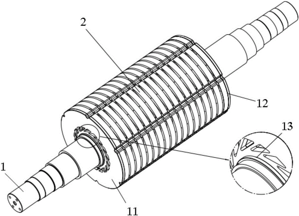
[0025] Such as figure 1 As shown, the unit magnetic pole structure of the permanent magnet motor rotor of the present invention mainly includes two parts of the rotating shaft 1 and the rotor core. The rotor core is divided into several unit poles 2 in the axial direction, and each unit pole 2 is manufactured separately and then fixed on the rotating shaft 1 . Radial ventilation slots are formed between adjacent unit poles 2 .

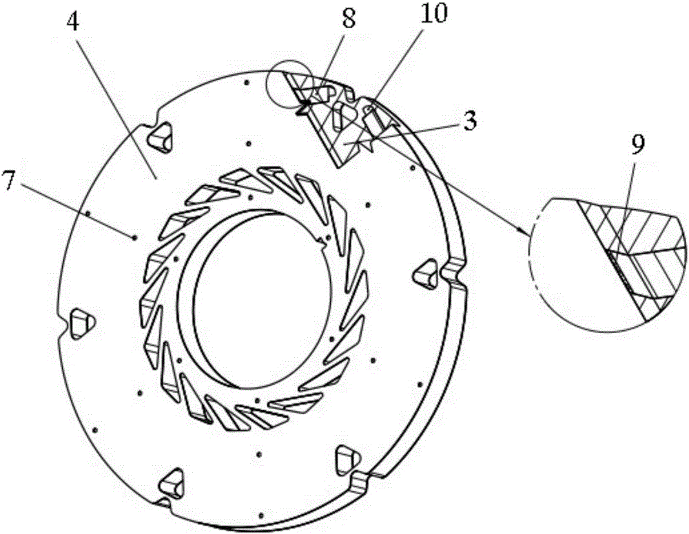
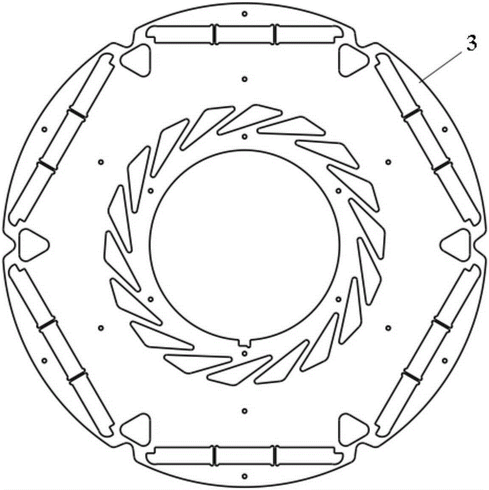
[0026] Such as figure 2 Shown is the structure of the unit pole 2. Each unit magnetic pole 2 is an independent rotor core, which is convenient for mass production and convenient for assembly. The composition of unit magnetic pole 2 includes rotor punching plate 3, iron core ventilation pressure plate 4, ventilation slot plate 5 (optional), ventilation slot piece 6 (optional), stainless steel rivet 7, magnetic st...


PUM


Abstract

The invention discloses a unit magnetic pole structure of a permanent magnet motor rotor. The unit magnetic pole structure comprises a rotating shaft and a rotor core, wherein the rotor core is axially divided into a plurality of independent unit magnetic poles, magnetic steel of each unit magnetic pole is axially fixed and sealed by a core ventilation pressure plate, magnetic pole cores are fixed by stainless steel rivets, and the unit magnetic poles are connected by ventilation slot plates and ventilation slot sheets. The unit magnetic pole structure has the advantages of novel structure, good performance and convenience in process, and is suitable for a high-speed rotating motor with high power density.

Description

technical field [0001] The invention relates to a rotor core structure of a permanent magnet motor, in particular to a permanent magnet built-in radial ventilation permanent magnet motor rotor structure suitable for high speed and high salt spray conditions, belonging to the technical field of permanent magnet motors. Background technique [0002] In high speed inner rotor permanent magnet motors, the permanent magnets are usually installed in the rotor core. There will be a certain gap between the permanent magnet and the rotor core, and the existence of these gaps will affect the firmness of the installation of the permanent magnet. Therefore, the usual process is to pour sealing resin into these gaps. In addition, if the permanent magnet is in direct contact with the air, the surface is easily corroded, which will affect the magnetic performance. Therefore, it is necessary to carry out secondary protection on the surface of the permanent magnet. [0003] For permanent m...

Claims


Application Information

Patent Timeline
Patent Type & Authority Applications(China)
IPC IPC(8): H02K1/32H02K1/28H02K1/27H02K15/02
Inventor 肖怡钦黄森林王小东仇薇王云陈恒峰郭强
Owner 愿景动力有限公司
Why Eureka
Try Eureka