Bracket

A technology of support feet and support rods, applied in the field of brackets, can solve the problems of cumbersome bracket construction, inconvenient storage and carrying, etc., and achieve the effects of protecting property safety, convenient carrying and adjustment, and protecting personal safety

Active Publication Date: 2016-01-27
KUNMING UNIV OF SCI & TECH
View PDF6 Cites 1 Cited by
  • Summary
  • Abstract
  • Description
  • Claims
  • Application Information

AI Technical Summary

Problems solved by technology

[0003] The purpose of the present invention is to provide a bracket to solve the problems of complicated construction of existing brackets, inconvenient storage and carrying.

Method used


Image

  • Bracket
  • Bracket
  • Bracket

Examples


Embodiment 1

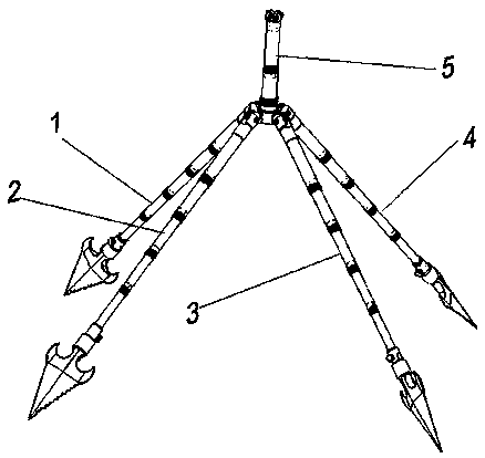
[0056] Embodiment 1: as Figure 1-26 As shown, a bracket includes an adjustable leg 1, an adjustable leg 2, an adjustable leg 3, an adjustable leg 4, and a support rod adjustment and fixing device 5;

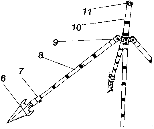
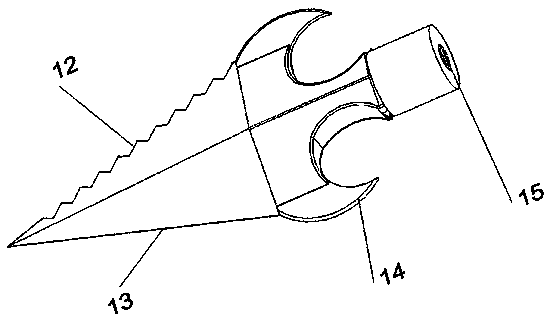
[0057] The structure of the adjustable leg one 1, the adjustable leg two 2, the adjustable leg three 3, and the adjustable leg four 4 are all the same and include a leg fixing mechanism 6, a rotary ball valve rotation mechanism 7, a telescopic rod height adjustment mechanism 8, a leg The root adjustment mechanism 9; wherein one end of the leg fixing mechanism 6 is fixed on the ground, the other end of the leg fixing mechanism 6 is screwed tightly to one end of the rotating ball valve rotating mechanism 7, and the other end of the rotating ball valve rotating mechanism 7 is connected to one end of the telescopic rod height adjusting mechanism 8 , the other end of the telescopic rod height adjustment mechanism 8 is connected with one end of the leg root adjustment mechanism 9 .

...

Embodiment 2

[0067] Embodiment 2: as Figure 1-26 As shown, a bracket includes an adjustable leg 1, an adjustable leg 2, an adjustable leg 3, an adjustable leg 4, and a support rod adjustment and fixing device 5;

[0068] The structure of the adjustable leg one 1, the adjustable leg two 2, the adjustable leg three 3, and the adjustable leg four 4 are all the same and include a leg fixing mechanism 6, a rotary ball valve rotation mechanism 7, a telescopic rod height adjustment mechanism 8, a leg Root adjustment mechanism 9; wherein one end of the leg fixing mechanism 6 is fixed on the ground, the other end of the leg fixing mechanism 6 is screwed and connected with one end of the rotary ball valve rotation mechanism 7, and the other end of the rotary ball valve rotation mechanism 7 is connected with one end of the telescopic rod height adjustment mechanism 8 , the other end of the telescopic rod height adjustment mechanism 8 is connected with one end of the leg root adjustment mechanism 9 ....

Embodiment 3

[0076] Embodiment 3: as Figure 1-26 As shown, a bracket includes an adjustable leg 1, an adjustable leg 2, an adjustable leg 3, an adjustable leg 4, and a support rod adjustment and fixing device 5;

[0077] The structure of the adjustable leg one 1, the adjustable leg two 2, the adjustable leg three 3, and the adjustable leg four 4 are all the same and include a leg fixing mechanism 6, a rotary ball valve rotation mechanism 7, a telescopic rod height adjustment mechanism 8, a leg The root adjustment mechanism 9; wherein one end of the leg fixing mechanism 6 is fixed on the ground, the other end of the leg fixing mechanism 6 is screwed tightly to one end of the rotating ball valve rotating mechanism 7, and the other end of the rotating ball valve rotating mechanism 7 is connected to one end of the telescopic rod height adjusting mechanism 8 , the other end of the telescopic rod height adjustment mechanism 8 is connected with one end of the leg root adjustment mechanism 9 .

...


PUM


Abstract

The invention relates to a bracket, and belongs to the field of outdoor activity equipment. An adjustable support leg 1, an adjustable support leg 2, an adjustable support leg 3 and an adjustable support leg 4 have the same structures, and comprise support leg fixing mechanisms, rotating ball valve rotating mechanisms, extension rod height adjusting mechanisms and support leg root adjusting mechanisms, wherein one ends of the support leg fixing mechanisms are fixed on the ground, and the other ends of the support leg fixing mechanisms are in threaded screwing connection with one ends of the rotating ball valve rotating mechanisms; the other ends of the rotating ball valve rotating mechanisms are connected with one ends of the extension rod height adjusting mechanisms; and the other ends of the extension rod height adjusting mechanisms are connected with one ends of the support leg root adjusting mechanisms. The bracket adjusts the fixed fork insertion direction in multiple angles, changes the height under different requirements, protects persons and properties from being exposed to the sun and rain, can be easily folded and shrunk to a smaller part in no use, and is convenient for carrying.

Description

technical field [0001] The invention relates to a bracket, which belongs to the field of outdoor sports equipment. Background technique [0002] At present, there is no special bracket that can be easily adjusted on the market. Only the skeleton support is generally used to achieve its effect, and smarter adjustment cannot be achieved. The disadvantages of them are first of all that they cannot be easily disassembled, and the construction is cumbersome. Complicated terrain, secondly, it is inconvenient to store and carry, and its function is relatively simple, which cannot well meet the functional needs of people in camping life. In addition, ordinary brackets cannot meet the requirements of adjusting heights according to different people's heights. Low, in the end, ordinary brackets are likely to cause more potential safety hazards, which pose a great threat to people's life safety and property safety. Our main purpose is to use a rotary ball valve device that can be rotat...

Claims


Application Information

Patent Timeline
Patent Type & Authority Applications(China)
IPC IPC(8): F16M11/32
Inventor 赵红波吴涛
Owner KUNMING UNIV OF SCI & TECH
Why Eureka
Try Eureka