Hook Production Line

A production line and hook technology, applied in the direction of conveyors, conveyor objects, transportation and packaging, etc., can solve the problems of poor connection in the previous process, affecting the bending effect, and small size of short rods, etc., to achieve good top bending effect, Improve feeding efficiency and ensure heating effect

Inactive Publication Date: 2017-11-03
建德市马目五金有限公司
View PDF12 Cites 2 Cited by
  • Summary
  • Abstract
  • Description
  • Claims
  • Application Information

AI Technical Summary

Problems solved by technology

[0002] Iron hooks are generally formed by cutting round iron rods into short rods according to the required length and then forging them after heating at high temperature; and heating the short rods generally needs to be carried out one by one, so a special conveying mechanism is required The neat short rods are transported to the heating mechanism one by one for heating, and then transported to the forging mechanism for forging; and the short rods are generally stacked in a disorderly manner due to their small size, so a special feeding mechanism is required to remove the disordered short rods. After the rods are neatly arranged, they are loaded onto the conveying mechanism; at present, commonly used forging devices generally have poor connection with the previous process, and high-temperature products need to be specially transported to the forging device for bending, and short rods have high temperatures, requiring special tools Handling, and high temperature short rods are easy to cool during the handling process, which affects the bending effect

Method used


Image

  • Hook Production Line
  • Hook Production Line
  • Hook Production Line

Examples


Embodiment Construction

[0044] The present invention will be described in further detail below in conjunction with the accompanying drawings, but it is not intended to limit the protection scope of the present invention.

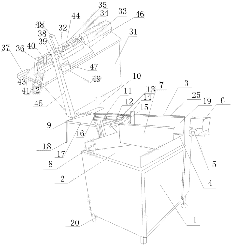
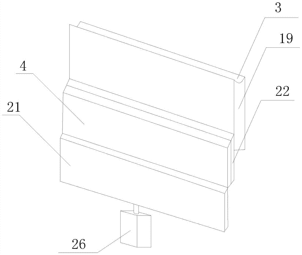
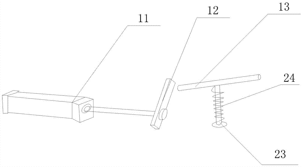
[0045] like Figure 1-5 As shown, a hook production line includes a short rod feeding and conveying heating device and a short rod bending device. The short rod feeding and conveying heating device includes a feeding mechanism, a conveying mechanism, a material breaking mechanism and a heating mechanism. The feeding mechanism includes The feeding bin 1, the feeding slope 2 and the supporting mechanism, the conveying mechanism includes the conveying sprocket 16, the conveying chain bracket 19, the conveying chain 3 and the conveying motor 5; the heating mechanism includes the electric heating tube 9 and the electric control box 10, the electric heating tube One end of 9 is connected with one end of the conveying chain 3. The supporting mechanism includes a supporting plate and a lif...


PUM


Abstract

The invention discloses a hook production line. The hook production line comprises a short rod feeding conveying and heating device and a short rod bending device. The short rod feeding conveying and heating device comprises a feeding mechanism, a conveying mechanism, a material cutting mechanism and a heating mechanism. The feeding mechanism comprises a feeding bin, a feeding slope and a material supporting mechanism. The conveying mechanism comprises a conveying chain wheel, a conveying chain supporting frame, a conveying chain and a conveying motor. The heating mechanism comprises an electrical heating tube and an electric cabinet. The material cutting mechanism comprises a material cutting air cylinder, a material cutting blocking rod and a material falling slop. The electric cabinet is internally provided with a programmable logic controller (PLC) and an electrical heating tube switch controlling the operation of the electrical heating tube. The short rod bending device comprises a material collection box, a conveying track, an ejection bending mechanism and a counter-ejection discharging mechanism. According to the hook production line, the heating effect on short rods is ensured, and the operation is convenient; the efficiency is high; meanwhile, the short rods heated at high temperature automatically fall into the conveying track and can be subjected to ejection bending after a short-distance conveyance, and time and labor are saved. In addition, the discharging is convenient and the ejection bending effect is good.

Description

technical field [0001] The invention relates to a production line of mechanical parts, in particular to a production line of hooks. Background technique [0002] Iron hooks are generally formed by cutting round iron rods into short rods according to the required length and then forging them after heating at high temperature; and heating the short rods generally needs to be carried out one by one, so a special conveying mechanism is required The neat short rods are transported to the heating mechanism one by one for heating, and then transported to the forging mechanism for forging; and the short rods are generally stacked in a disorderly manner due to their small size, so a special feeding mechanism is required to remove the disordered short rods. After the rods are neatly arranged, they are loaded onto the conveying mechanism; at present, commonly used forging devices generally have poor connection with the previous process, and high-temperature products need to be speciall...

Claims


Application Information

Patent Timeline
Patent Type & Authority Patents(China)
IPC IPC(8): B65G47/14B65G47/29B21D7/00
CPCB21D7/00B65G47/1492B65G47/29B65G2201/0217B65G2205/04
Inventor 祝跃敏
Owner 建德市马目五金有限公司
Why Eureka
Try Eureka