Energy consumption device and switch gear

A technology of energy-consuming devices and switchgear, which is applied in the field of vibration reduction and vibration reduction, can solve problems such as closing and bouncing of moving contacts, and achieve the effects of avoiding rebound, strong deceleration and promotion, and optimizing dynamic performance

Inactive Publication Date: 2016-03-16
陈鸽
View PDF11 Cites 0 Cited by
  • Summary
  • Abstract
  • Description
  • Claims
  • Application Information

AI Technical Summary

Problems solved by technology

However, the damping force generated by the energy dissipation device will promote the reverse movement of the moving contact, and often cause the moving contact to bounce when closing.

Method used


Image

  • Energy consumption device and switch gear
  • Energy consumption device and switch gear
  • Energy consumption device and switch gear

Examples


Embodiment approach 1

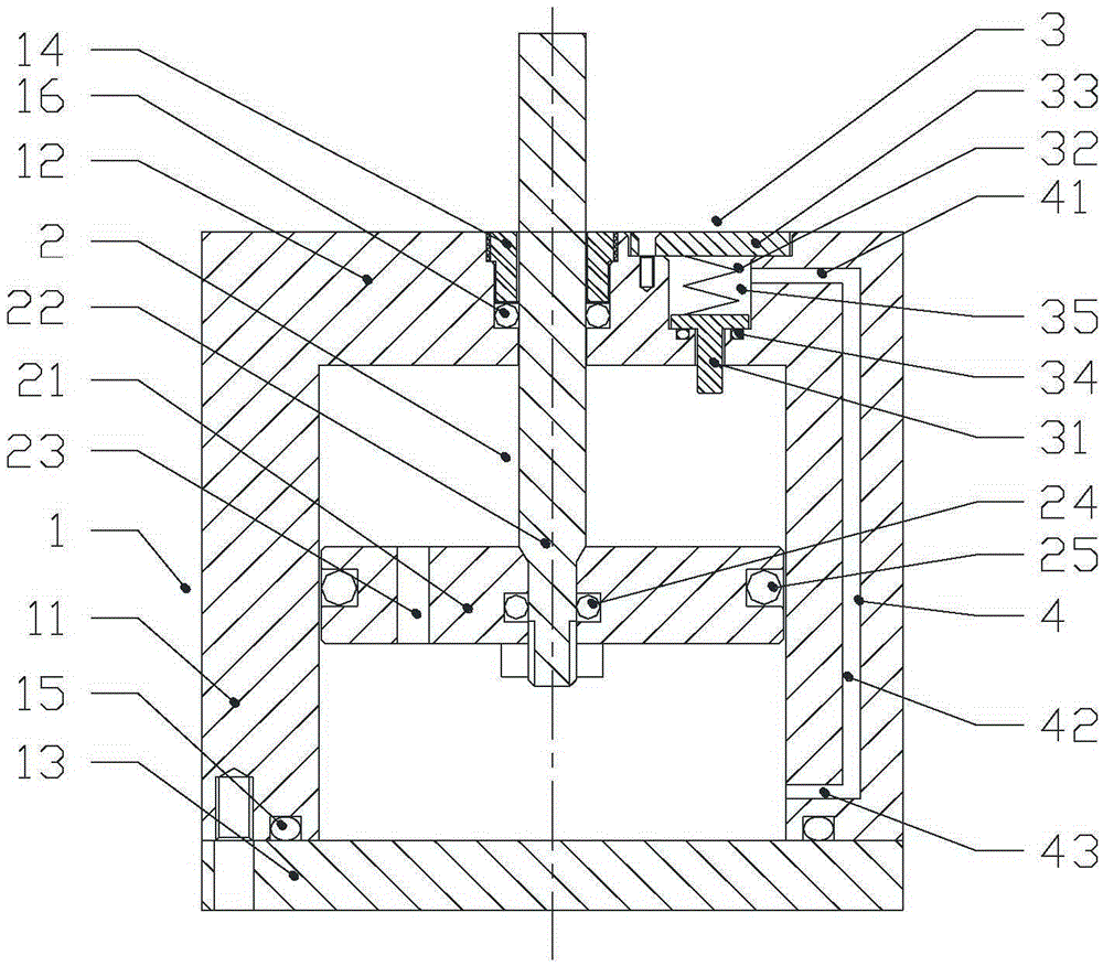
[0035] A kind of energy consumption device of the present invention, as figure 1 As shown, it includes a cylinder body 1, a piston mechanism 2, a pressure relief device 3 and a channel 4. The cylinder body 1 includes a first end cover 12, a cylinder barrel 11 and a second end cover 13, the first end cover 12 is sealed and fixed on the top end of the cylinder barrel 1, further, the first end cover 12 and the cylinder The barrel 1 is integrally formed; the second end cover 13 is fixed on the bottom end of the cylinder barrel 1 by bolts, and the second end cover 13 and the bottom end of the cylinder barrel 1 are sealed by the first sealing ring 15 . The piston mechanism 2 includes a piston 21 and a piston rod 22 . The piston 21 is arranged inside the cylinder 1, and the side surface of the piston 21 and the inner surface of the cylinder 11 are sealed by a fourth sealing ring 25, and the piston 21 can move along the axis of the cylinder 1 relative to the cylinder 1. sports. The...

Embodiment approach 2

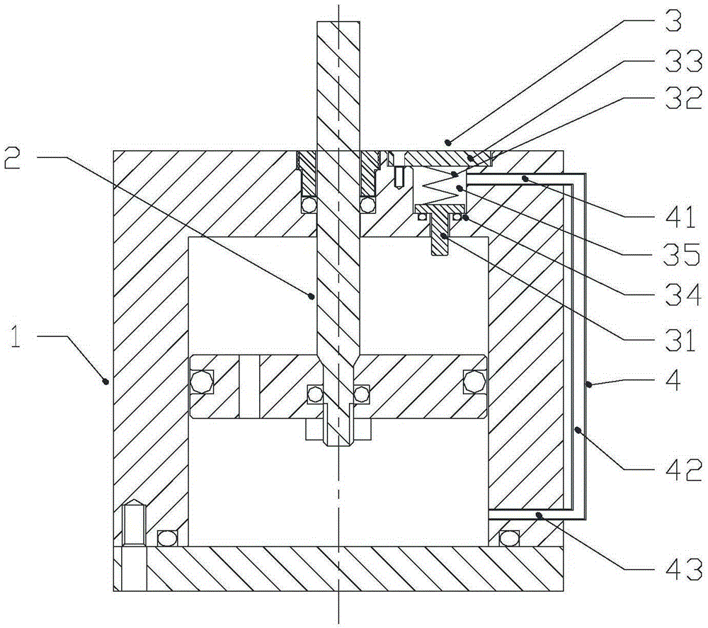
[0040] The difference between Embodiment 2 and Embodiment 1 is only: figure 2 As shown, the channel 4 includes a first channel 41 , a second channel 42 and a third channel 43 . The first channel 41 is built in the first end cover 12 and is in sealing communication with the pressure relief chamber 35 of the pressure relief device 3, distributed along the radial direction of the first end cover 12; the second channel 42 is arranged outside the cylinder body 1 , distributed along the axial direction of the cylinder 11; the third channel 43 is arranged in the cylinder wall of the cylinder 11 and is located on the side of the second end cover 13 and is in sealing communication with the second chamber, along the radial direction of the cylinder 11 distributed. The first channel 41 , the second channel 42 and the third channel 43 are sequentially sealed and communicated with each other.

Embodiment approach 3

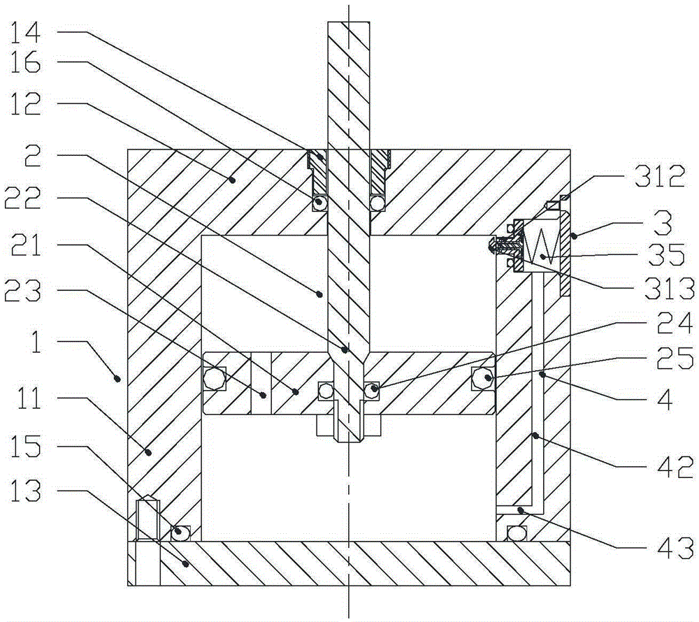
[0042] The difference between Embodiment 3 and Embodiment 1 is only: image 3 As shown, the pressure relief device 3 is assembled on the upper end of the cylinder wall of the cylinder 11 , that is, on the side of the first end cover 12 . The pressure relief chamber 35 of the pressure relief device 3 is arranged on the upper end of the cylinder wall of the cylinder 11, which is composed of a bottom wall and a side wall, and the top opening is opened at the outer end of the cylinder 11. Here, the pressure relief device 3 The axis direction determines the top and bottom of the spatial orientation of the pressure relief device 3 . The part of the spool stem 312 of the pressure relief spool 31 that extends into the cylinder body 1 is a spherical crown, and can also be inclined or cam-shaped, so that the side wall of the piston can squeeze the pressure relief spool conveniently, without causing any damage to the pressure relief spool. Collision damage to the sidewall of the piston....


PUM


Abstract

The invention discloses an energy consumption device and a switch gear. The energy consumption device comprises a cylinder body, a piston, a piston rod and a pressure relief device. The cylinder body comprises a first end cover, a cylinder barrel and a second end cover. One end of the piston rod penetrates the first end cover and extends into the cylinder body so as to be fixed to the piston in the cylinder body. An inner cavity of the cylinder body is divided into a first cavity body and a second cavity body located on the first end cover side through the piston. The pressure relief device is assembled on the cylinder body and a valve element rod of an internally-arranged pressure relief valve element of the pressure relief device extends into the first cavity body. The switch gear comprises a single-pole switch which is connected with the energy consumption device in the axial direction. When a switch is turned on, at the last section of a vacuum envelope moving contact stroke, damping is released through the energy consumption device, the situation that a turned-on moving contact of the switch gear is promoted by damping force to pop up is avoided, and the turn-on performance is improved. The pressure relief device is arranged on the cylinder body of the energy consumption device, and the pressure relief valve element is installed, maintained and replaced conveniently.

Description

technical field [0001] The invention relates to an energy dissipation device, in particular to an easy-to-maintain energy dissipation device that generates damping at the front end of the stroke and releases damping at the end of the stroke, and a switchgear using the energy dissipation device, belonging to the field of vibration reduction. Background technique [0002] At present, new and higher requirements are continuously put forward for the opening and closing performance of high-voltage and low-voltage switchgear, and the opening and closing time is required to be shorter without arcing. This will inevitably make the moving contact of the vacuum bubble, which is the core component of the high and low voltage mechanical switch, have a higher speed when opening and closing, and the moving contact will not bounce when closing, and will not discharge and arc. No rebound, no discharge arcing. When the switch is closed, the high-speed moving moving contact of the vacuum bub...

Claims


Application Information

Patent Timeline
Patent Type & Authority Applications(China)
IPC IPC(8): F15B13/02H02B1/04
CPCF15B13/02H02B1/04
Inventor 陈鸽
Owner 陈鸽
Why Eureka
Try Eureka