Device for assembling cams on a camshaft pipe

A camshaft and cam technology, applied in the direction of cams, valve devices, components with teeth, etc., to optimize the installation space, achieve rationalization, and save space

Inactive Publication Date: 2016-03-16
MAHLE INT GMBH
View PDF5 Cites 4 Cited by
  • Summary
  • Abstract
  • Description
  • Claims
  • Application Information

AI Technical Summary

Problems solved by technology

[0004] However, the known device has the disadvantage that, because of the clamps, all the cams must be clamped in the same way and must also be fixed in the correct angular position by rotating the camshaft tubes

Method used


Image

  • Device for assembling cams on a camshaft pipe
  • Device for assembling cams on a camshaft pipe
  • Device for assembling cams on a camshaft pipe

Examples


Embodiment Construction

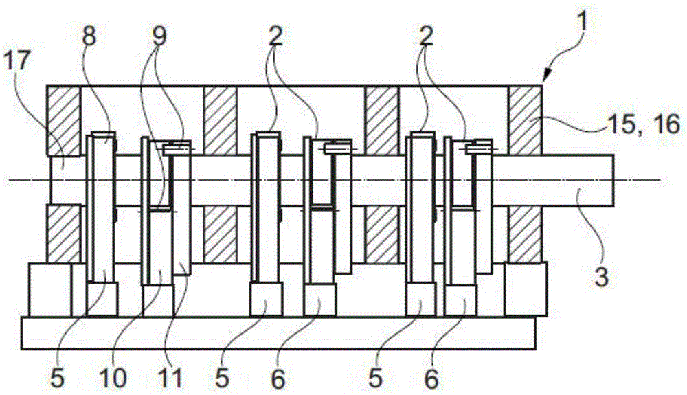
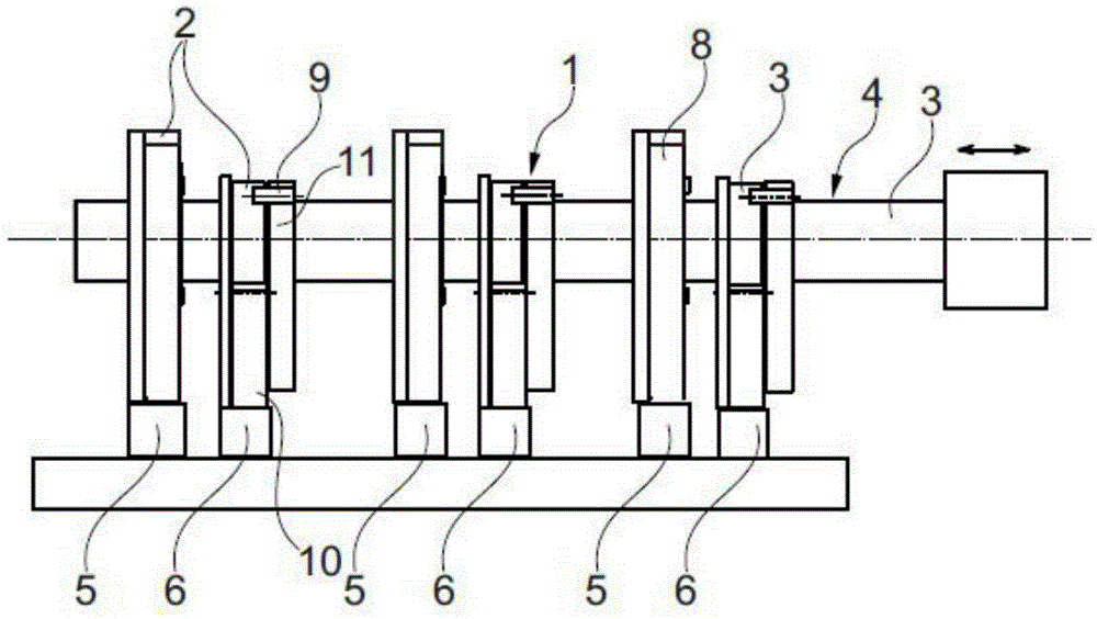
[0044] according to Figures 1 to 3 According to the device 1 of the present invention, the camshaft tube 3 for assembling the cam 2 to the camshaft 4 includes at least one first clamp 5 and a second clamp 6 for clamping and holding the cam 2 during the assembly process.

[0045] In this case, each Figures 1 to 3 All the devices 1 include three first clamps 5 and three second clamps 6 .

[0046] In this case, all fixtures 5, 6 according to the above Figures 1 to 3 Can be fitted to cam 2 from the same direction and moved in the same direction to align with camshaft tube 3.

[0047] In the case shown, the individual clamps 5 , 6 can be adjusted vertically in the manner described so that the cam 2 fixed to the clamps 5 , 6 faces the cam hole 7 aligned with the camshaft tube 3 .

[0048] According to the invention, the second clamp 6 can now hold the cam 2 rotated by 90° relative to the cam 2 held by the first clamp 5 .

[0049] Thus, not only is a particularly space-optimiz...


PUM


Abstract

The invention relates to a device (1) for assembling cams (2) on a camshaft pipe (3) of a camshaft (4), comprising at least one first gripper (5) and a second gripper (6) for gripping and holding the cams (2) during the assembly process. The at least two grippers (5, 6) can be fitted with cams (2) from the same direction and can be moved in the same direction into alignment with the camshaft pipe (3). It is essential to the invention that the second gripper (6) allows a cam (2) to be gripped in a pivoted manner by 90 DEG relative to the first gripper (5). In this manner, a rational assembly of the cams (2) is possible with a device (1) which has a simultaneously optimized installation space.

Description

technical field [0001] The invention relates to a tube, a camshaft tube for assembling a cam to a camshaft, comprising at least one first clamp and a second clamp for clamping and holding the cam during assembly according to the preamble of claim 1 . [0002] Furthermore, the invention relates to a method for thermally connecting a cam to a camshaft tube using said device and to a second clamp for said device. Background technique [0003] A general arrangement for the automated production of camshafts is well known and has been used industrially for a long time. [0004] However, a disadvantage of the known device is that, because of the clamps, all the cams must be clamped in the same way and must also be fixed in the correct angular position by rotating the camshaft tube. [0005] Therefore, just a continuous connection of the cams to the camshaft tube is usually possible. Contents of the invention [0006] The problem addressed by the present invention is therefore ...

Claims


Application Information

Patent Timeline
Patent Type & Authority Applications(China)
IPC IPC(8): F01L1/047F16H53/02
CPCF01L1/047F16H53/025F01L2001/0471B23P2700/02F01L2303/01B23P11/025
Inventor 弗兰克·多泰尔托马斯·弗伦德尔安东尼奥·梅农纳斯特凡·斯泰彻尔
Owner MAHLE INT GMBH
Why Eureka
Try Eureka