card connector

A technology of card connectors and electric permanent magnets, which is applied in the direction of connection, components of connection devices, coupling devices, etc., can solve the problems of complex structure of the card ejection mechanism, inconvenient operation, and inconformity with the development trend of connector miniaturization, etc. Achieve the effect of convenient and reliable operation and simple structure

Active Publication Date: 2019-06-28
FOXCONN (KUNSHAN) COMPUTER CONNECTOR CO LTD +1
View PDF7 Cites 0 Cited by
  • Summary
  • Abstract
  • Description
  • Claims
  • Application Information

AI Technical Summary

Problems solved by technology

The structure of the above-mentioned ejection mechanism is complicated, which does not conform to the miniaturization development trend of the connector
and inconvenient to operate

Method used


Image

  • card connector
  • card connector
  • card connector

Examples


Embodiment Construction

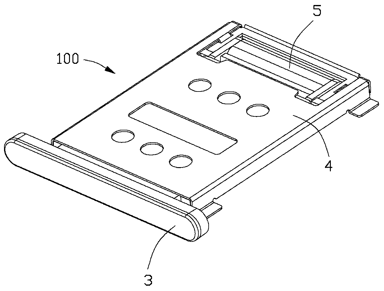
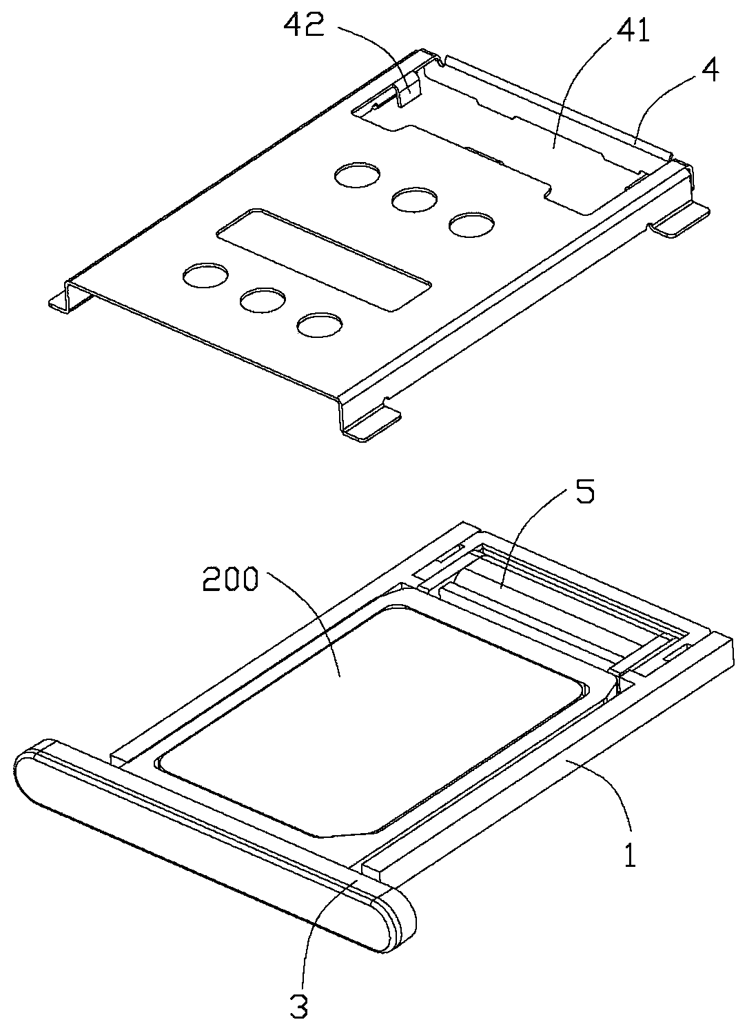
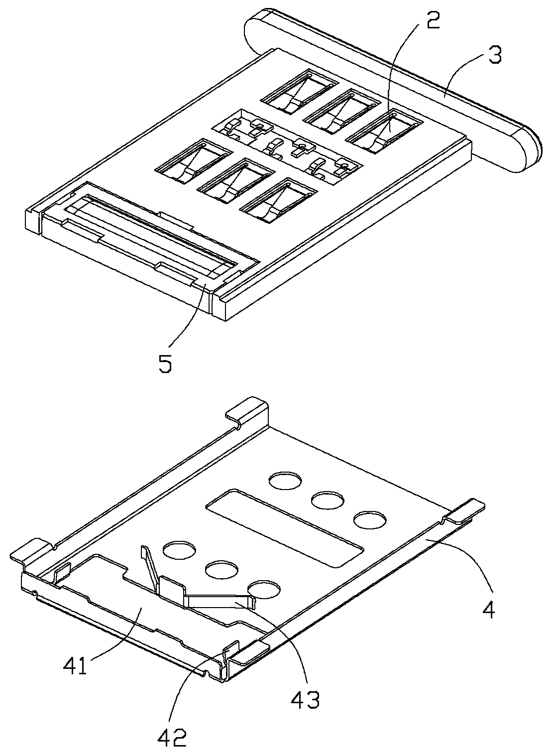
[0027] Please refer to Figure 1 to Figure 6 As shown, the card connector 100 of the present invention is used to insert an electronic card 200 . The card connector 100 includes an insulating body 1, a plurality of terminals 2 held in the insulating body 1, a shielding cover 4 that is fastened on the insulating body 1 to form an insertion space 11 with the insulating body 1, and a cover 4 in the insertion space. The drawer seat 3 inserted in 11, and the electric permanent magnet 5 accommodated in the insulating body 1.

[0028] The insulating body 1 is provided with a receiving space 12 located in front of the insertion space 11 to accommodate the electro-permanent magnet 5 .

[0029] The upper surface of the shielding cover 4 is provided with an opening 41 , a pair of locking pieces 42 extending into the opening 41 , and a pair of elastic arms 43 behind the opening 41 and extending backward.

[0030] The electro-permanent magnet 5 in the first embodiment includes a housing ...


PUM


Abstract

The invention discloses a card connector comprising an insulating body, a plurality of terminals held into the insulating body, a shielding cover buckled onto the insulating body to form an insertion space between the shielding cover and the insulating body, and a drawer base inserted into or pulled out of the insertion space. The card connector further comprises an electric permanent magnet. When the drawer base is inserted into the insertion space, a current in a first direction is applied to the electric permanent magnet, and the magnetic force of the electric permanent magnet is increased to absorb the drawer base. When a card withdraws, a current in a second direction opposite to the first direction is applied to the electric permanent magnet, and the magnetic force of the electric permanent magnet is decreased to release the drawer base.

Description

【Technical field】 [0001] The invention relates to a card connector, in particular to a card connector which utilizes electric permanent magnets to realize card insertion or card withdrawal. 【Background technique】 [0002] The card ejecting mechanism of the card connector in the prior art generally adopts a heart-shaped groove mechanism or a mechanism in which a thimble pushes a push rod. The U.S. Patent No. 7865210 issued on January 4, 2011 discloses that the locking mechanism of the card connector is set as a pair of elastic arm structures inside the receiving cavity, and the card ejecting mechanism is set as a rotating part near the opening. Pushing one end of the rotating part makes the other end rotate toward the opening to drive the drawer base to exit the opening. The above-mentioned ejection mechanism has a complex structure and does not conform to the development trend of miniaturization of connectors. And the operation is inconvenient. [0003] U.S. Patent No. 36...

Claims


Application Information

Patent Timeline
Patent Type & Authority Patents(China)
IPC IPC(8): H01R13/633
Inventor 庄顺荣曾威达张皓丞
Owner FOXCONN (KUNSHAN) COMPUTER CONNECTOR CO LTD
Why Eureka
Try Eureka