Button cell stacking device

A button battery and mounting slot technology, applied in battery pack components, circuits, electrical components, etc., can solve problems such as affecting the layout of other components, occupying space, and unable to continue to record time.

Active Publication Date: 2019-08-16
SUZHOU LANGCHAO INTELLIGENT TECH CO LTD
View PDF4 Cites 0 Cited by
  • Summary
  • Abstract
  • Description
  • Claims
  • Application Information

AI Technical Summary

Problems solved by technology

[0003] The RTC circuit is powered by a button battery. In the traditional circuit structure, only one button battery is set. The length of the recording time after power failure is

Method used


Image

  • Button cell stacking device
  • Button cell stacking device
  • Button cell stacking device

Examples


Embodiment Construction

[0022] The core of the present invention is to provide a button battery stacking device, which uses the deep space of the fixing base to stack button batteries, and increases the recording time of the RTC circuit of the device without occupying too much extra space structure.

[0023] In order to enable those skilled in the art to better understand the technical solution of the present invention, the button battery stacking device of the present invention will be described in detail below in conjunction with the accompanying drawings and specific implementation methods.

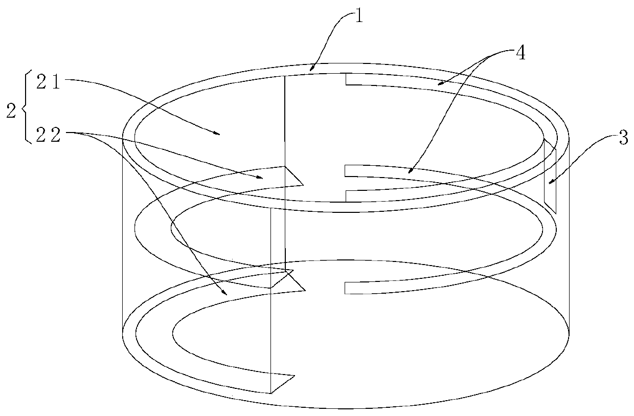
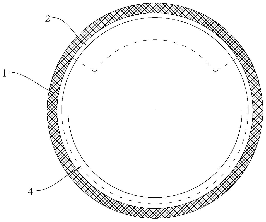
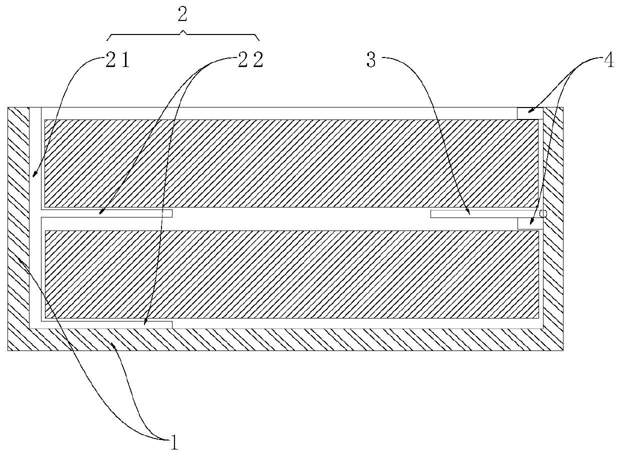
[0024] Such as figure 1 Shown is the structural representation of the button battery stacking device of the present invention; figure 2 with image 3 They are respectively a top view and a front sectional view of the button battery stacking device of the present invention; including a fixing base 1, on which a mounting groove is provided, and the mounting groove has sufficient depth to accommodate at least ...


PUM

PropertyMeasurementUnit
Widthaaaaaaaaaa

Abstract

The invention discloses a button cell stacking device. A mounting groove has a depth sufficient to accommodate at least two stacked button cells. The side wall of the mounting groove is provided witha fixed support piece and an elastic support piece. The fixed support piece is fixed in the mounting groove. The elastic support piece can be overturned with respect to the side wall of the mounting groove. The elastic support piece and the fixed support piece support the button cells in cooperation. The elastic support piece is overturned and attached to the side wall of the mounting groove by anelastic reset piece. When button cells are required to be installed, the elastic support piece is overturned to a position perpendicular to the side wall of the mounting groove, and the elastic supporting piece can support the button cells. A stopping boss disposed on the side wall of the mounting groove, in cooperation with the elastic support piece, presses and stops the button cells from bothsides in order to fix the button cells. The button cell stacking device can accommodate the stacked button cells, utilizes the depth space of a fixing seat, does not occupy the lateral space of a PCB,does not affect the installation of other components, and prolongs the recording time of a RTC circuit of a device.

Description

technical field [0001] The invention relates to the field of electronic equipment manufacturing, and further relates to a button battery stacking device. Background technique [0002] In order to record the time, the server equipment needs to be equipped with an RTC (Real-time Clock) circuit, which is generally an integrated circuit, so it is also called a clock chip. It is often used in personal computers, servers or embedded systems to record time when the device is powered off. [0003] The RTC circuit is powered by a button battery. In the traditional circuit structure, only one button battery is set. The length of the recording time after power failure is determined by the power of the button battery. If two or more button batteries are arranged, it will take up twice or more additional space and affect the layout of other components. [0004] For those skilled in the art, how to increase the recording time of the RTC circuit of the device without occupying too much ex...

Claims


Application Information

Patent Timeline
IPC IPC(8): H01M2/10H01M2/20
CPCH01M50/216H01M50/50Y02E60/10
Inventor 陈治宇
Owner SUZHOU LANGCHAO INTELLIGENT TECH CO LTD
Why Eureka
Try Eureka