Power generation device in lock body of door lock

A power generation device and lock body technology, which is applied in construction locks, machines/engines, mechanical power generated by physical force, etc., can solve the problems of large size, large overall size, and increased panel size, etc., and achieve small size, compact structure, and extended The effect of using time

Pending Publication Date: 2016-06-08
北京摇光智能科技有限公司
View PDF10 Cites 5 Cited by
  • Summary
  • Abstract
  • Description
  • Claims
  • Application Information

AI Technical Summary

Problems solved by technology

[0002] At present, the known electronic locks with power generation function have two methods: photovoltaic cell power generation and mechanical power generation, wherein the photovoltaic cell power generation is relatively small, and cannot be used in an emergency when the battery power is exhausted; mechanical power generation is generated by a generator, and the existing The mechanical power generation device for the electronic door lock is placed in the front panel, which causes the size of the front panel to become larger, or the size itself is larger, which is inconvenient to install and use
[0003] Patent No. 201410413752.0 "Hand-operated power-generating door lock" and patent No. 201310285068.4 "An electronic door lock with a hand-operated charging device" installed the power generation device in the lock panel, which increas

Method used


Image

  • Power generation device in lock body of door lock
  • Power generation device in lock body of door lock
  • Power generation device in lock body of door lock

Examples


example 1

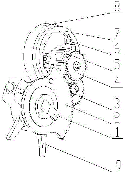
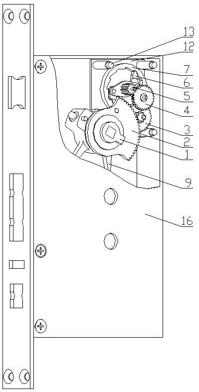
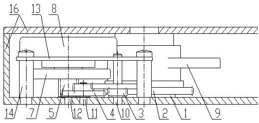
[0025] See Figure 1 to Figure 5 as shown, Figure 1 to Figure 5 Shown is a specific embodiment of a power generating device in a door lock body, including an input shaft 1, an input gear 2, a first-stage duplex gear 3, a second-stage duplex gear 4, a pawl installation gear 5, and a pawl 6 , ratchet rotor 7, generator stator 8, clutch shaft assembly 9, primary gear shaft 10, secondary gear shaft 11, pawl shaft 12, generator fixing plate 13, generator mounting stud 14, lock body housing 16 Wherein one-stage duplex gear 3, second-stage duplex gear 4, pawl mounting gear 5, pawl 6, ratchet rotor 7 constitute a speed-increasing transmission mechanism, and clutch shaft assembly 9 is composed of clutch shaft 91, pin 92, spring 93 , retaining ring 94; the input shaft 1 is inserted into the inner hole of the clutch shaft 91, there is a groove on the input shaft 1 whose width is slightly larger than the diameter of the end of the pin 92, the input gear 2 is a sector gear, and the input...

example 2

[0031] For instance two, please refer to Image 6 As shown, the second example is a variant of the first example, which is basically the same as Figure 1 to Figure 5 The specific embodiments shown are the same, and the same components use the same reference numerals. Compared with the example one, the second example cancels the pawl installation gear 5, the pawl 6, the ratchet rotor 7, and the pawl shaft 12, and adds a belt The gear rotor 15; the first-stage duplex gear 3 and the second-stage duplex gear 4 form a speed-increasing transmission mechanism.

[0032] The external door handle drives the input shaft 1 to rotate through the square hole on the input shaft 1, the input shaft 1 drives the input gear 2 to rotate, the input gear 2 drives the pinion on the first-stage double gear 3 to rotate, and the first-stage double gear 3 The large gear drives the pinion of the secondary duplex gear 4 to rotate, and the large gear of the secondary duplex gear 4 drives the gear of the ...

example 3

[0035] Example three see Image 6 As shown, the third example is a variant of the first example, which is basically the same as Figure 1 to Figure 5 The specific embodiments shown are the same, and the same components use the same reference numerals. Compared with the first example, the third example adds a screw 16; the input shaft 1 and the input gear 2 do not transmit torque through bosses and holes, but through Screws 16 are held together to transmit torque.


PUM


Abstract

A power generation device in a lock body of a door lock is characterized by comprising an input shaft, an input gear, a gearing-up mechanism, a micro generator, a clutch rotating shaft component and a lock body casing. Except the lock body casing, other parts are installed in the lock body, a sector gear is installed on the input shaft to rotate together with the input shaft, the input shaft and an outer door handle are coaxial, and the input shaft is driven by the outer door handle. An outside mechanism controls connection relations of the clutch rotating shaft component and the input shaft by controlling a clutch pin on the clutch rotating shaft component. When a door does not need to be opened, the outer door handle drives the input shaft to rotate, drives the generator is generate electricity and does not drive the clutch rotating shaft component to rotate. When the door needs to be opened, the outer door handle drives the input shaft to rotate, drives the generator to generate electricity and drives the clutch rotating shaft component to rotate.

Description

Technical field [0001] The invention involves the field of electronic door locks, especially a lock with a built -in generator. Background technique [0002] At present, the electronic locks of Gongzhi's power generation function have two ways: photovoltaic battery power generation and mechanical power generation. Among them, photovoltaic battery power generation power is small and cannot be used when the battery power is exhausted. Mechanical power generation is generated by generators.The mechanical power generation device for electronic door locks is placed in the front panel, causing the size of the front panel to become larger, or it is large in size, and it is inconvenient to install. [0003] The patent of the application number 201410413752.The installation of other components inside the panel, of which; 201310285068.4 patent "An electronic door lock with a hand -shaken charging device" only gives the schematic diagram of the charging device in the instructions, and no sp...

Claims


Application Information

Patent Timeline
IPC IPC(8): F03G5/02E05B47/00
CPCF03G5/02E05B47/0012E05B2047/002E05B2047/0026E05B2047/0035
Inventor 郑超余棉梓程峰
Owner 北京摇光智能科技有限公司
Why Eureka
Try Eureka