Al technical title is built by PatSnap Al team. It summarizes the technical point description of the patent document.
A shredder, single-shaft technology, applied in the shredder field, can solve the problems of tool wear, high cost, complex structure, etc., and achieve the effect of improving work efficiency, not easy to jam, and good shredding effect.
Active Publication Date: 2018-02-16
GUANGZHOU 3E MACHINERY
View PDF10 Cites 0 Cited by
Summary
Abstract
Description
Claims
Application Information
AI Technical Summary
This helps you quickly interpret patents by identifying the three key elements:
Problems solved by technology
Method used
Benefits of technology
Problems solved by technology
Generally, twin-shaft shredders are used in industry, the quality is unstable, the noise is loud, and the shredding effect is not good.
There are also some industries that use single-shaft shredders, but the existing single-shaft shredders have complex structures and high costs.
Moreover, when the material to be shredded is waste tires, since the tires have steel wires, the tires with steel wires are likely to cause tool wear
When the tool is worn out, it is necessary to disassemble the shredder and hoist the main shaft to replace the tool. It can be seen that the maintenance of the shredder is extremely inconvenient
Method used
Image
Click on the blue label to locate the original text in one second.
Reading with bidirectional positioning of images and text.
Examples
Embodiment Construction
[0028] Embodiments of the present invention are described in detail below:
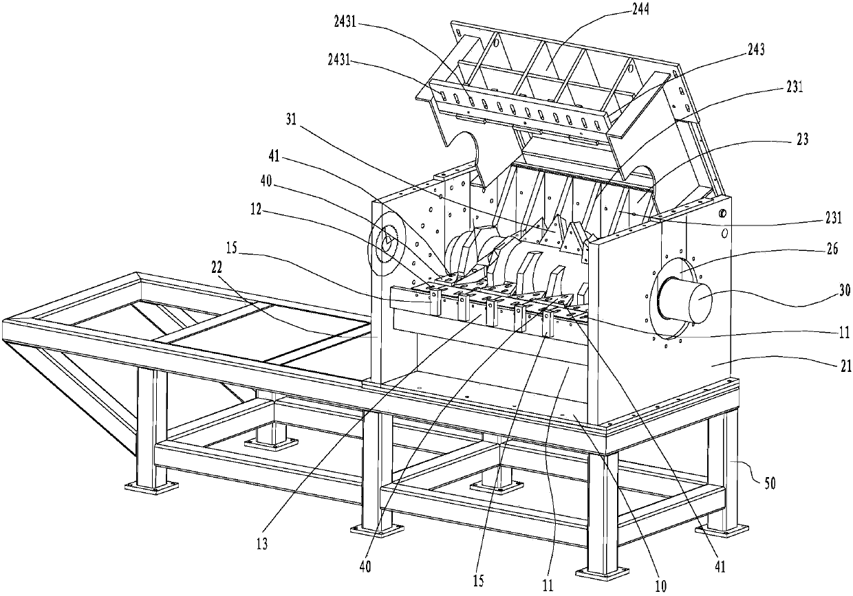
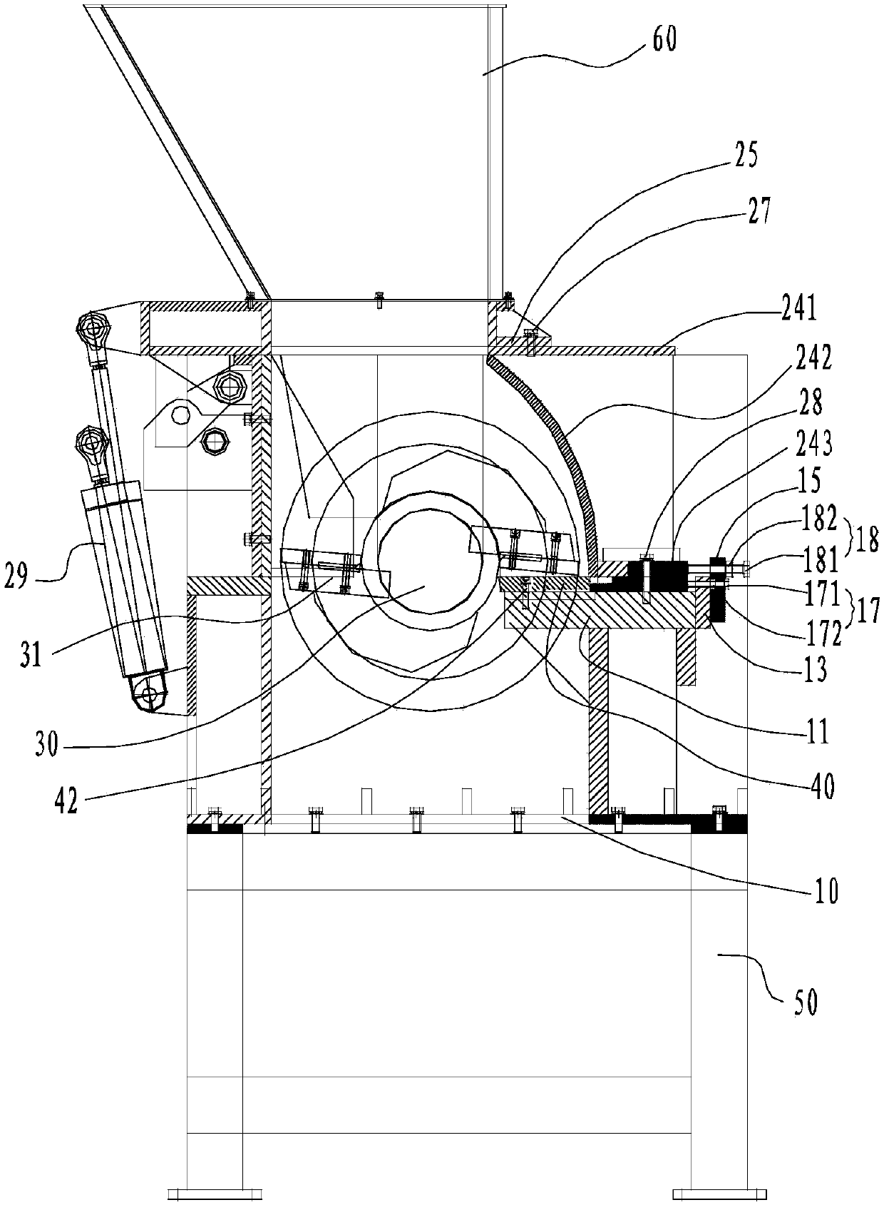
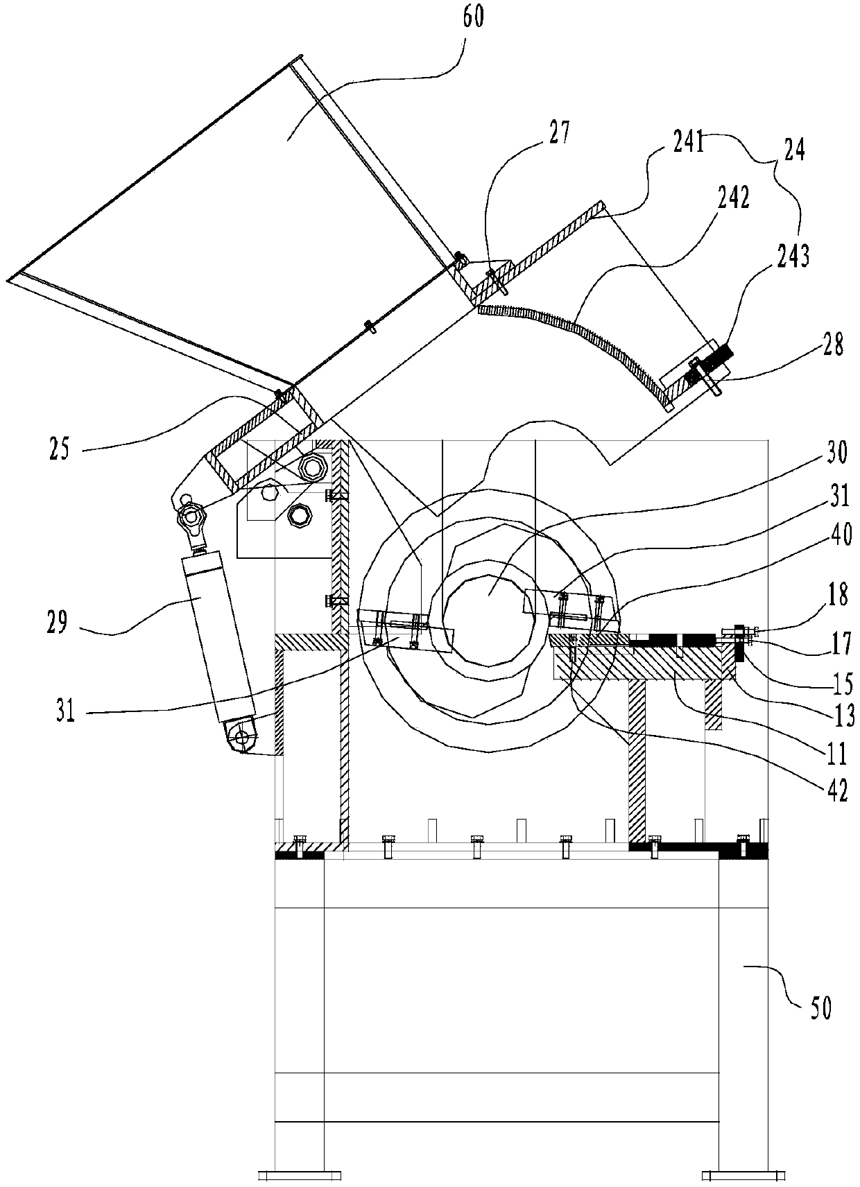
[0029] Such as figure 1 As shown, the single-shaft shredder of the present invention includes: a base 10, a first support plate 21, a second support plate 22, a first side plate 23, a second side plate 24, a top plate 25, a rotating shaft 30, Moving knife body 31 and fixed knife body 40.
[0030] The first support plate 21 and the second support plate 22 are arranged side by side on the base 10 at intervals, and both the first support plate 21 and the second support plate 22 are provided with bearing holes 26 . Both ends of the first side plate 23 are respectively connected to the first support plate 21 and the second support plate 22 . The top board 25 is rotatably connected to the first side board 23 , and the top board 25 is connected to the second side board 24 . The second side panel 24 is detachably connected to the base 10 . The first side board 23 , the second side board 24 , the top board...
PUM
Abstract
The invention discloses a single-shaft shredding machine. The single-shaft shredding machine comprises a base, a first supporting plate, a second supporting plate, a first side plate, a second side plate, a carrier plate, a rotating shaft, a movable cutter body and a fixed cutter body, wherein the first supporting plate and the second supporting plate are arranged on the base side by side at intervals; bearing holes are formed in the first supporting plate and the second supporting plate; the two ends of the first side plate are respectively connected to the first supporting plate and the second supporting plate; the carrier plate is rotatably connected to the first side plate and is connected to the second side plate; the second side plate is detachably connected to the base; the rotating shaft is rotatably arranged the first supporting plate and the second supporting plate through the bearing holes; and one end of the rotating shaft extends out from the bearing holes and then is connected to a torque output mechanism. The single-shaft shredding machine has the beneficial effects that the second side plate and the carrier plate are easy to overturn and open together around the first side plate; and the maintenance efficiency of the fixed cutter body and the movable cutter body on the rotating shaft is high.
Description
technical field [0001] The invention relates to a shredder, in particular to a single-shaft shredder. Background technique [0002] Shredders are generally used to process unprocessed raw materials or scraps, such as various plastics, rubber, tires, fibers, wood, iron drums, waste electrical appliances, waste cables, industrial scraps, commercial and industrial waste, mixed construction waste , paper and cardboard, plastic film, textiles, domestic waste, medical waste and other solid or hollow materials. Generally, twin-shaft shredders are used in industry, the quality is unstable, the noise is loud, and the shredding effect is not good. There are also some industries that use single-shaft shredders, but the existing single-shaft shredders have complex structures and high costs. And when the material that shreds is waste tires, because the tire is with steel wire, the tire with steel wire will easily cause cutter wear. When the tool is worn out, the shredder needs to be d...
Claims
Application Information
Patent Timeline
Application Date:The date an application was filed.
Publication Date:The date a patent or application was officially published.
First Publication Date:The earliest publication date of a patent with the same application number.
Issue Date:Publication date of the patent grant document.
PCT Entry Date:The Entry date of PCT National Phase.
Estimated Expiry Date:The statutory expiry date of a patent right according to the Patent Law, and it is the longest term of protection that the patent right can achieve without the termination of the patent right due to other reasons(Term extension factor has been taken into account ).
Invalid Date:Actual expiry date is based on effective date or publication date of legal transaction data of invalid patent.