Single fiber bidirectional time division multiplexing optical amplifier

A single-fiber two-way, amplifying device technology, applied in the direction of electromagnetic wave transmission system, electrical components, transmission system, etc., can solve the problems of high pump power, low efficiency, increase the implementation and operation cost of optical fiber time transfer system, and improve the signal quality. Noise ratio, suppression of multiple amplification effects

Active Publication Date: 2017-12-26
SHANGHAI JIAOTONG UNIV
View PDF3 Cites 0 Cited by
  • Summary
  • Abstract
  • Description
  • Claims
  • Application Information

AI Technical Summary

Problems solved by technology

The improvement of the signal-to-noise ratio of this scheme is at the expense of the asymmetry of the two-way transmission delay. It is necessary to calibrate the asymmetry of the two-way transmission delay on the amplified link, which will greatly increase the implementation and operation costs of the optical fiber time transfer system. , and the total uncertainty of the calibration increases with the increase of the number of amplifiers and the extension of the transmission distance; Czech CESNET[4, V.S.a.J.Vojtěch,"Time and Frequency Transfer Using Amplified Optical Links," in EFTF 2014,2014,pp.325 -328.] et al. use distributed Raman amplifiers to optically amplify bidirectionally transmitted time signals. Although a single fiber can guarantee the bidirectional symmetry of link transmission delay, noise such as Rayleigh scattering will also be amplified multiple times. , there are also problems such as high pump power, low efficiency and dependence on the polarization direction of the input optical signal.

Method used


Image

  • Single fiber bidirectional time division multiplexing optical amplifier
  • Single fiber bidirectional time division multiplexing optical amplifier

Examples


Embodiment Construction

[0018] The present invention will be further described below in conjunction with drawings and embodiments. Examples provide the detailed implementation of the present invention and specific workflow, but the protection scope of the present invention is not limited to the following examples.

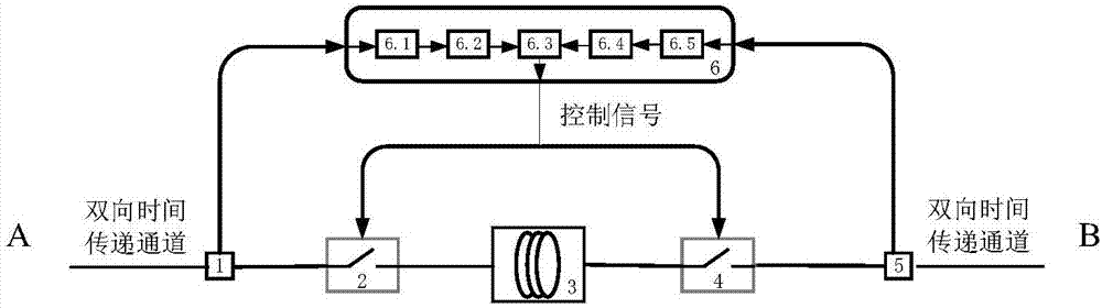
[0019] see first figure 1 , figure 1 It is a schematic structural view of the single-fiber bidirectional time-division multiplexing optical amplifier device of the present invention. It can be seen from the figure that the single-fiber bidirectional time-division multiplexing optical amplifier device of the present invention comprises: a first optical splitter 1, a first magneto-optical switch 2, A single-fiber bidirectional optical amplifier 3 without an isolator, a second magneto-optical switch 4, a second optical splitter 5, and a control unit 6; the control unit 6 consists of the first photoelectric conversion module 6.1, the first Composed of identification module 6.2, timing contr...


PUM


Abstract

The invention relates to a single-fiber bidirectional time-division multiplexing light amplification apparatus in a fiber time frequency transmission field. The single-fiber bidirectional time-division multiplexing light amplification apparatus comprises a first optical splitter, a first magneto-optical switch, a single-fiber bidirectional optical amplifier without an isolator, a second magneto-optical switch, a second optical splitter and a control unit. On the basis of a relationship between a light passing direction of a magneto-optical switch and a control voltage, light passing directions of the magneto-optical switches are controlled according to a detected optical signal transmission direction and thus optical signals in forward transmission and backward transmission on a time transfer channel enter the single-fiber bidirectional optical amplifier at different time, so that same-fiber same-wave bidirectional amplification of optical signals with timing signals in a BTDM-SFSW time transfer link is realized and the link symmetry is guaranteed to the greatest extent. With unidirectional light passing characteristic of the magneto-optical switch, the influence on a fiber time transfer performance by multiple times of amplification of the noise like rayleigh scattering can be avoided effectively.

Description

technical field [0001] The invention relates to an optical amplifying device, in particular to a single-fiber bidirectional time-division multiplexing optical amplifying device. Background technique [0002] High-precision time transfer technology has important application value in the fields of satellite navigation, aerospace, deep space exploration, geological surveying and mapping, and basic physical quantity measurement. At present, time transfer technologies based on satellites, such as GPS Precise Point Positioning (PPP) and Two-Way Satellite Time Transfer (TWSTFT), can achieve time transfer accuracy on the order of ns. With the invention and operation of clock sources with higher stability and uncertainty such as optical clocks, these transmission technologies can no longer meet the needs of scientific research and social development. A space-based time transfer technology (T2L2) based on the principle of satellite laser ranging with a theoretical uncertainty of bett...

Claims


Application Information

Patent Timeline
Patent Type & Authority Patents(China)
IPC IPC(8): H04B10/297
CPCH04B10/297
Inventor 张浩吴龟灵陈建平
Owner SHANGHAI JIAOTONG UNIV
Why Eureka
Try Eureka