High-precision optical fiber time transfer bidirectional optical amplification method and device

A time transfer and amplifying device technology, applied in optical fiber transmission, bidirectional transmission, optics, etc., can solve the problems of high pump power, increase the implementation and operation cost of fiber time transfer system, low efficiency, etc., to ensure bidirectional symmetry, The effect of high-precision optical fiber time transfer

Active Publication Date: 2018-03-09
SHANGHAI JIAO TONG UNIV
View PDF3 Cites 0 Cited by
  • Summary
  • Abstract
  • Description
  • Claims
  • Application Information

AI Technical Summary

Problems solved by technology

The improvement of the signal-to-noise ratio of this scheme is at the expense of the asymmetry of the two-way transmission delay, and the asymmetry of the two-way transmission delay of the amplifier needs to be calibrated, and the total error of the calibration increases linearly with the increase in the number of amplifiers; Czech CESNET [4] and others use distributed Raman amplifiers to optically amplify bidirectionally transmitted time signals. Although the bidirectional symmetry of link transmission delay can be guaranteed, noise such as Rayleigh scattering will also be optically amplified multiple times. There are problems such as high pump power, low efficiency and dependence on the polarization direction of the input optical signal
In addition, the upgrading and transformation of the optical amplification equipment of the existing optical fiber communication network in order to implement the above scheme will greatly increase the implementation and operation costs of the optical fiber time transfer system

Method used


Image

  • High-precision optical fiber time transfer bidirectional optical amplification method and device
  • High-precision optical fiber time transfer bidirectional optical amplification method and device

Examples


Embodiment Construction

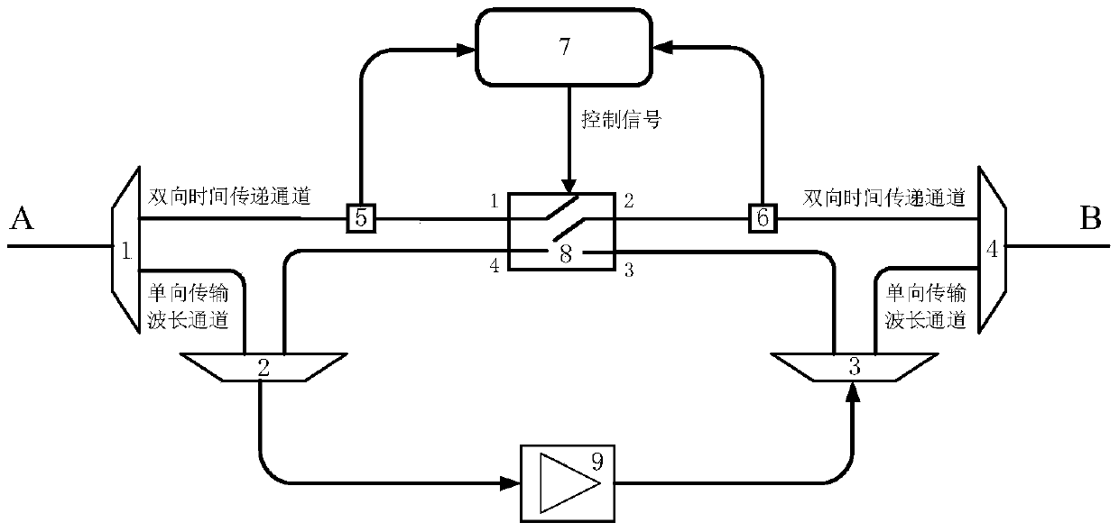
[0034] Attached below figure 1 A specific implementation example of the present invention is given. This example provides the detailed implementation and specific workflow of the present invention, but the protection scope of the present invention is not limited to the following examples.

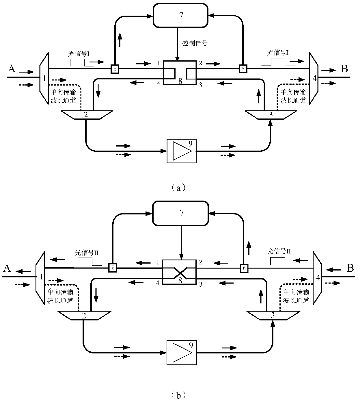
[0035] In this embodiment, the transmission direction of the unidirectional transmission wavelength channel is from A to B. In the wavelength channel of two-way time transmission, the timing signal transmitted is 1PPS, the transmission direction of the optical signal I carrying 1PPS is from A to B, that is, the forward direction, and the transmission direction of the optical signal II carrying 1PPS is from B to A, that is, the reverse direction . Optical signal I and optical signal II are time-divisionally transmitted in the link. In the embodiment, the 2×2 optical switch adopts a mechanical optical switch whose switching time is on the order of milliseconds, and the unidirectional optic...


PUM


Abstract

The invention discloses a bidirectional optical amplification method and device for high-precision fiber-optic time transfer. The bidirectional time transfer channel is selected from fiber-optic transfer channels through the wavelength separator / combiner. By controlling the 2×2 optical switch, the optical signals transferred along two opposite directions transmitted forth and back are made to enter into the unidirectional optical amplifier at different times along with other optical signals transferred along the unidirectional transmission wavelength channel. Thereby, the bidirectional optical amplification for the optical signals carrying timing signal over a single fiber with the same wavelength (BTDM-SFSW) based time transfer link is realized. The bidirectional delay symmetry is guaranteed to the maximum extent by allowing the time signals to be transmitted back and forth using the same wavelength over a single fiber. Meanwhile, the noises suffered in the systems employing single fiber bidirectional optical amplifiers, such as double Rayleigh backscattering, are effectively suppressed. Furthermore, the amplification scheme for time transfer is compatible with the unidirectional optical amplification in conventional telecom networks and does not affect the amplifications of other unidirectional transmission wavelength channels in the fiber link.

Description

technical field [0001] The invention relates to an optical amplification method and an implementation device in the field of optical fiber time-frequency transfer, in particular to a high-precision optical fiber time transfer bidirectional optical amplification method and device. Background technique [0002] High-precision time transfer technology has important application value in the fields of satellite navigation, aerospace, deep space exploration, geological surveying and mapping, and basic physical quantity measurement. At present, time transfer technologies based on satellites, such as GPS Common View (CV) and Two-Way Satellite Time Transfer (TWSTFT), can achieve time transfer accuracy on the order of ns. With the invention and operation of clock sources with higher stability and uncertainty such as optical clocks, these technologies can no longer meet the needs of scientific research and social development. A space-based time transfer technology (T2L2) based on the ...

Claims


Application Information

Patent Timeline
Patent Type & Authority Patents(China)
IPC IPC(8): G02F1/39
CPCG02F1/395H04B10/2589H04B10/2971
Inventor 吴龟灵张浩陈建平
Owner SHANGHAI JIAO TONG UNIV
Why Eureka
Try Eureka