Multi-band MIMO cell phone antenna with simple decoupling structure

A simple structure, mobile phone antenna technology, applied in the direction of the antenna, the structure of the radiating element, the device that makes the antenna work in different frequency bands at the same time, etc. Market demand, the effect of multiple working frequency bands

Inactive Publication Date: 2016-08-10
CENT SOUTH UNIV
View PDF7 Cites 7 Cited by
  • Summary
  • Abstract
  • Description
  • Claims
  • Application Information

AI Technical Summary

Problems solved by technology

[0003] The present invention proposes a multi-band MIMO mobile phone antenna with a simple decoupling structure, and its purpose is to solve the problem that the space reserved for the antenna in the mobile terminal is limited and the working frequency band of the existing antenna is less

Method used


Image

  • Multi-band MIMO cell phone antenna with simple decoupling structure
  • Multi-band MIMO cell phone antenna with simple decoupling structure
  • Multi-band MIMO cell phone antenna with simple decoupling structure

Examples


Embodiment Construction

[0030] The present invention will be further described below in conjunction with the accompanying drawings and embodiments.

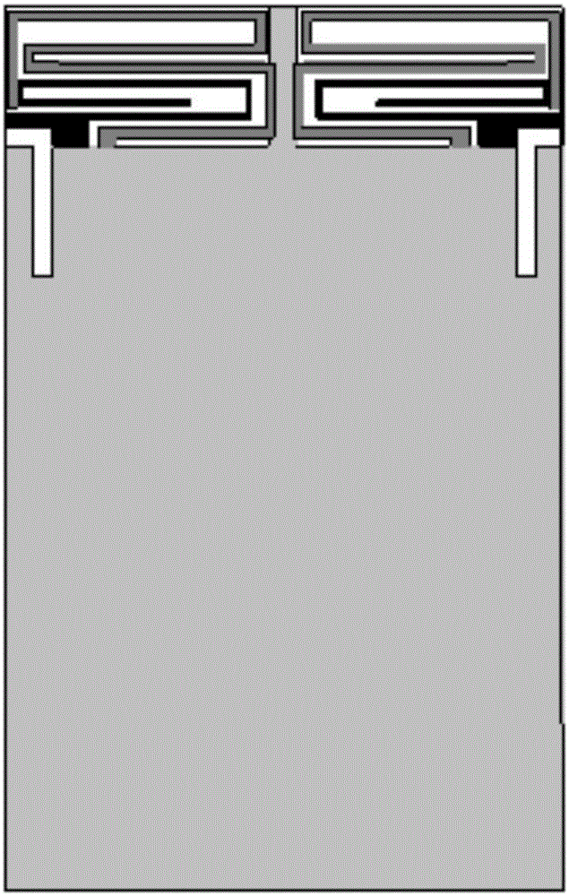
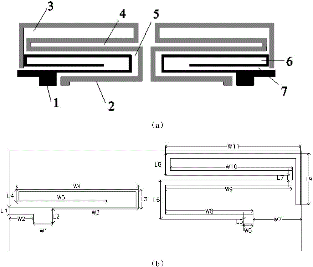
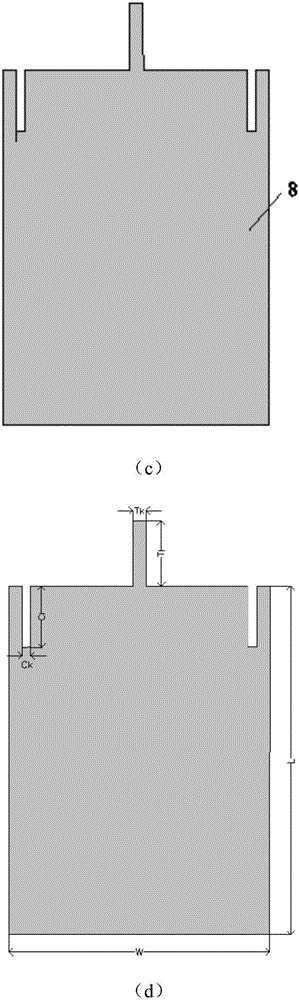
[0031] Such as figure 1 and figure 2 As shown, a multi-band MIMO mobile phone antenna with a simple decoupling structure includes a ground plate 8, a dielectric substrate and two groups of multi-branch bent ring radiation patches symmetrically arranged on the dielectric substrate;

[0032] The two groups of multi-branch bending ring radiation patches are respectively fixed on the upper ends of the left and right sides of the dielectric substrate along the edge of the dielectric substrate;

[0033] Each group of multi-branch bending ring radiation patch includes two bending parts, namely the first bending structure 1 and the second bending structure 2, and the first bending structure 1 is arranged at the bend of the second bending structure 2. in the fold gap;

[0034] The ground plate is fixed on the bottom end of the reverse side of the dielectric...


PUM


Abstract

The invention discloses a multi-band MIMO cell phone antenna with a simple decoupling structure. The antenna comprises a grounding plate, a medium substrate, and two groups of multi-branch bending ring radiation chips symmetrically arranged on the medium substrate. The two groups of multi-branch bending ring radiation chips are fixedly provided at the top ends of the left edge and the right edge of the medium substrate along the edges of the medium substrate. Each group of the multi-branch bending ring radiation chips comprises two bending parts. The grounding plate is fixedly arranged at the bottom of the back face of the medium plate. The width of the grounding plate is identical to that of the medium substrate and the grounding plate is provided with two concave rectangular grooves and a protruding rectangle. The two concave rectangular grooves are symmetrical to each other with the vertical axis of the medium plate in the middle. The protruding rectangle is right in the middle of the grounding plate. According to the invention, the combination of grooves and a protruding rectangle enables the decoupling of a MIMO structure so that an antenna can meet the requirement of a cell phone on all frequency bands while ensuring the coupling is low.

Description

technical field [0001] The invention relates to the technical field of terminal antennas, in particular to a multi-band MIMO mobile phone antenna with simple decoupling structure. Background technique [0002] In a multipath transmission environment, MIMO (Mitiple-Input Mitiple-Output) technology can greatly improve the capacity and communication quality of wireless channels without increasing the working bandwidth and transmission power, so MIMO technology It has become a research hotspot in the field of wireless communication, and has attracted the attention of scholars in the field of wireless communication. One of the core technologies of the fourth generation mobile communication system). As a key component of mobile communication systems, the design of MIMO mobile phone antennas has been paid attention to. Multiple antennas are the basis of MIMO systems, and the correlation of signals received by each antenna unit will seriously affect the performance of MIMO systems...

Claims


Application Information

Patent Timeline
Patent Type & Authority Applications(China)
IPC IPC(8): H01Q1/38H01Q5/20
CPCH01Q1/38H01Q5/20
Inventor 董健余夏苹邓联文施荣华
Owner CENT SOUTH UNIV
Why Eureka
Try Eureka