An electromagnetic tooth clutch

A clutch and cogging technology, which is applied in the field of electromagnetic cogging clutches, can solve problems affecting the meshing of movable end gears and fixed end gears, system noise, weak spring buffering effect, etc., so as to facilitate torque transmission, stable transmission structure, and easy The effect of surface contact

Active Publication Date: 2019-07-19
JING JIN ELECTRIC TECH HEZE CO LTD
View PDF1 Cites 1 Cited by
  • Summary
  • Abstract
  • Description
  • Claims
  • Application Information

AI Technical Summary

Problems solved by technology

Since the adsorption force of the electromagnet is generated instantaneously, the moving speed of the moving end gear is often relatively fast. At this time, it will collide violently with the positioning plate, resulting in significant system noise
Although the pre-compressed spring between them can play a certain buffering effect, the elastic modulus of the spring should not be too large, otherwise it will affect the meshing between the movable end gear and the fixed end gear, so the buffering effect of the spring is very weak. Does not significantly reduce system noise

Method used


Image

  • An electromagnetic tooth clutch
  • An electromagnetic tooth clutch
  • An electromagnetic tooth clutch

Examples


Embodiment 1

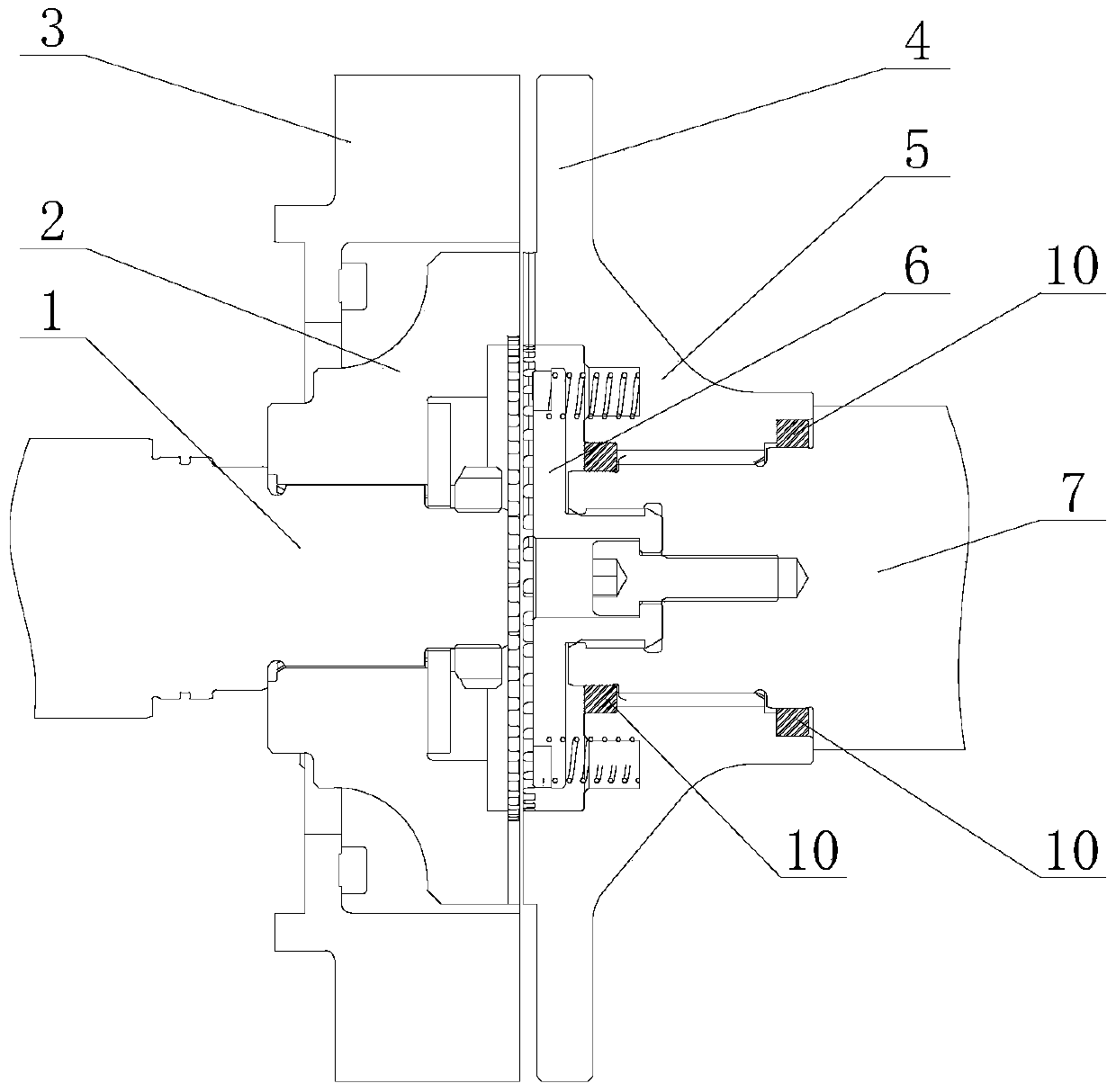
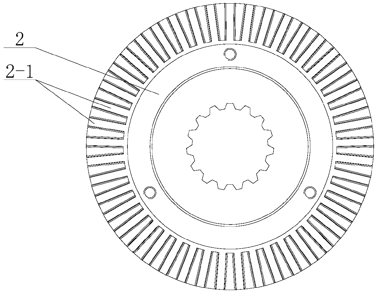
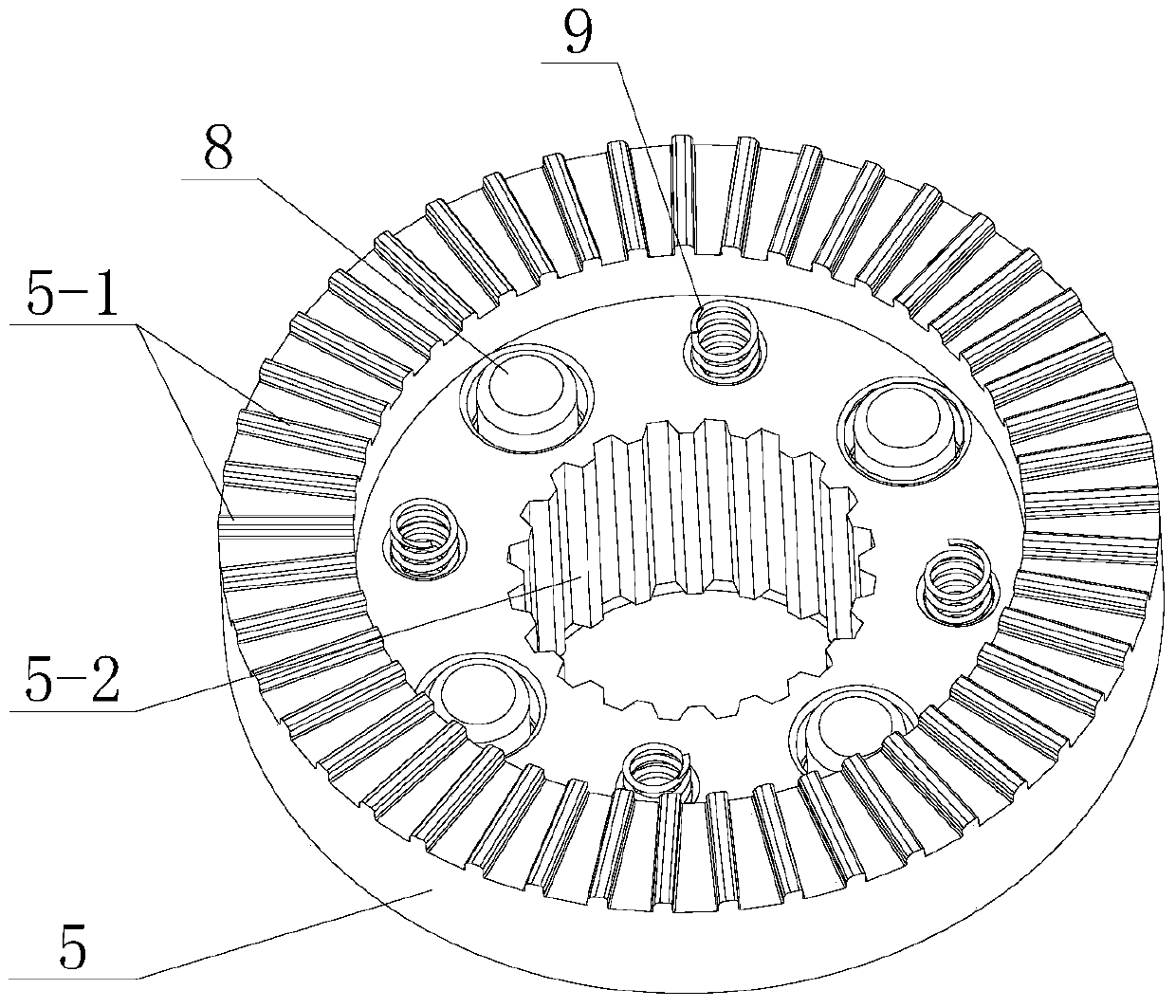
[0037] Such as figure 1 , figure 2 , image 3 Shown is one of the embodiments of the present invention. In this embodiment, the electromagnetic toothed clutch includes a movable toothed sleeve 5 and a fixed toothed sleeve 2 for meshing transmission. The movable toothed sleeve 5 is provided with end face transmission teeth 5-1. The fixed tooth sleeve 2 is correspondingly provided with an end face tooth groove 2-1, and the transmission tooth 5-1 is of equal thickness along the tooth length direction, and the tooth groove 2-1 meshing with the transmission tooth 5-1 is fan-shaped along the groove length direction, that is, the tooth groove The two sides of 2-1 have a predetermined included angle, and the width gradually increases along the radial direction of the fixed tooth sleeve 2 , and gradually decreases along the radial direction of the fixed tooth sleeve 2 .

[0038] Due to the combination of equal-thickness transmission teeth and sector-shaped tooth grooves, the transmi...

Embodiment 2

[0054] Such as Figure 8 As shown, it is the second embodiment of the present invention. In this embodiment, the armature 4 and the movable gear sleeve 5 are manufactured separately and combined together.

[0055] After the armature 4 and the movable gear sleeve 5 are made separately, they can be welded together, or bolted together, or bolts and welded can be used simultaneously. The armature 4 is made of No. 10 steel. Steel No. 10 is more sensitive to magnetic response.


PUM


Abstract

The present invention discloses an electromagnetic dog clutch, comprising a movable gear sleeve and a fixed toothed sleeve that are engaged to transmit power The movable gear sleeve is provided with contrate transmission teeth or tooth spaces, and the fixed toothed sleeve is correspondingly provided with contrate tooth spaces or transmission teeth. The transmission teeth have a uniform thickness in a direction of tooth length, tooth spaces that engage with the transmission teeth have a sector-shape in a direction of tooth space length, and the width of two sides of the tooth spaces gradually increases outwardly along the radial direction of the fixed toothed sleeve and gradually decreases inwardly along the radial direction of the fixed toothed sleeve. By employing the engagement of transmission teeth of uniform thickness and sector-shaped tooth spaces, the transmission teeth can more easily engage with the tooth spaces, and more easily realize surface contact, which facilities moment transmission and facilities the stability of the transmission structure.

Description

technical field [0001] The invention relates to an electromagnetic tooth clutch, in particular to a transmission tooth structure of the electromagnetic tooth clutch and a centering structure of a movable tooth sleeve. Background technique [0002] Because some models of new energy vehicles have engines, motors, and transmissions at the same time, the space for vehicle layout is very limited. In order to reduce fuel consumption, improve system efficiency, optimize control strategies, and realize switching between different working modes, power on-off must be used. mechanism. Because the traditional clutch includes a pressure plate, a driven plate, a diaphragm spring, a release bearing, a rocker arm and a booster mechanism, etc., it involves many parts, is heavy, has many failure points, and is inconvenient to maintain. [0003] In the prior art, there are electromagnetic dog clutches that can replace traditional clutches. For example, an electromagnetic dog clutch is disclos...

Claims


Application Information

Patent Timeline
Patent Type & Authority Patents(China)
IPC IPC(8): F16D27/118F16D27/14
CPCF16D27/118F16D27/14F16D2027/008F16D2011/008F16D2027/007F16D11/14F16D43/2024
Inventor 余平王婷叶晓
Owner JING JIN ELECTRIC TECH HEZE CO LTD
Why Eureka
Try Eureka