Control system and method of charger

A control method and technology for a control system, applied in the field of charger control system, can solve the problems of non-linear change and adjustment being difficult to meet, unable to perform inspection and inspection immediately, unable to see real-time waveforms, etc., so as to improve safe operation and analyze fault records. Accurate, Convenience-enhancing Effects

Active Publication Date: 2016-11-09
ZHUZHOU CSR TIMES ELECTRIC CO LTD
View PDF5 Cites 0 Cited by
  • Summary
  • Abstract
  • Description
  • Claims
  • Application Information

AI Technical Summary

Problems solved by technology

[0002] At present, the battery charger needs high-precision output control, but the connected battery load may change greatly, and often requires the hardware to set the potentiometer to adjust to meet the requirements, and the adjustment of the potentiometer can only be a linear change, for nonlinear changes The adjustment is difficult to meet; when the charger is maintained and debugged, it needs to be debugged and maintained through the RS232 interface and the program is downloaded through the JTAG port. At the bottom, when running online, you can only observe the basic status information through the display, and you cannot see the real-time waveform. To detect the real-time waveform, you need to connect an oscilloscope and other testing equipment, which increases the difficulty of detection and will also affect driving; when the charger is running online When a fault occurs, it is often not possible to check it immediately. The vehicle needs to be repaired after returning to the warehouse. The situation on the site is becoming more and more complicated. In order to analyze the cause of the fault as soon as possible, it is necessary for the charger itself to record more and more relevant information. And the collection frequency is also required to be higher and higher

Method used


Image

  • Control system and method of charger
  • Control system and method of charger
  • Control system and method of charger

Examples


Embodiment Construction

[0034] The present invention will be further described below in conjunction with the accompanying drawings and specific embodiments.

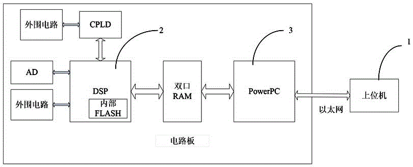
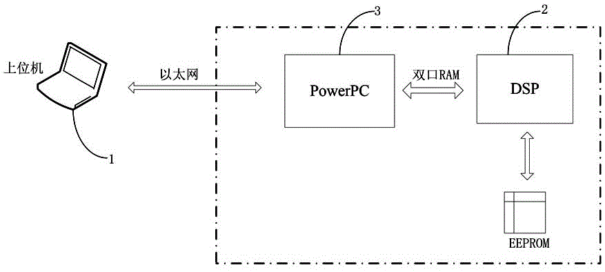
[0035] Such as figure 1 As shown, the charger control system of this embodiment includes a DSP unit 2, a PowerPC unit 3 and a host computer 1, and the DSP unit 2 and the PowerPC unit 3 communicate with each other through a dual-port RAM unit; the host computer 1 and the PowerPC unit 3 They are connected through Ethernet communication for remote real-time monitoring and maintenance of the charger. In the charging machine control system of the present invention, the upper computer 1 is connected to the charging machine through the Ethernet, and can remotely monitor and maintain the charging machine in real time, thereby improving the operation safety of the charging machine and improving the convenience of equipment maintenance.

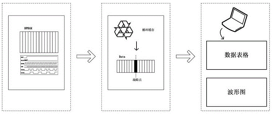
[0036] In this embodiment, the DSP unit 2 is connected with a storage unit, which is used for cyclically storing the...


PUM


Abstract

The invention discloses a control system of a charger. The control system comprises a DSP unit, a PowerPC unit and an upper computer. The DSP unit and the PowerPC unit carry out mutual communication by a dual-port RAM unit; and the upper computer and the PowerPC unit are in communication connection by an Ethernet network, thereby realizing remote real-time monitoring and maintenance on a charger. In addition, the invention also discloses a control method of a charger. The upper computer sends a command signal to the PowerPC unit by an Ethernet network; the PowerPC unit b receives the command signal from the upper computer and then sends the signal to the DSP unit by the dual-port RAM unit; and the DSP executes a corresponding motion based on the command signal of the upper computer. The control method and the control system have advantages of remote monitoring, convenient maintenance, and stable operation.

Description

technical field [0001] The invention mainly relates to the technical field of chargers, in particular to a charger control system and method. Background technique [0002] At present, the battery charger needs high-precision output control, but the connected battery load may change greatly, and often requires the hardware to set the potentiometer to adjust to meet the requirements, and the adjustment of the potentiometer can only be a linear change, for nonlinear changes The adjustment is difficult to meet; when the charger is maintained and debugged, it needs to be debugged and maintained through the RS232 interface and the program is downloaded through the JTAG port. At the bottom, when running online, you can only observe the basic status information through the display, and you cannot see the real-time waveform. To detect the real-time waveform, you need to connect an oscilloscope and other testing equipment, which increases the difficulty of detection and will also affe...

Claims


Application Information

Patent Timeline
Patent Type & Authority Applications(China)
IPC IPC(8): H02J7/00B60L11/18
CPCH02J7/0021H02J7/0036H02J7/0047B60L53/14H02J7/0071H01M10/4257Y02T90/16Y04S30/12Y02T10/70Y02T90/167Y02T10/7072Y02T90/14Y02E60/10
Inventor 曾明高严志勇袁芳羊利芬彭学标钟源张小勇周帅
Owner ZHUZHOU CSR TIMES ELECTRIC CO LTD
Why Eureka
Try Eureka