
Grinding device for carving knife for root carving
A knife sharpening device and carving knife technology, applied in the direction of grinding driving device, grinding/polishing safety device, grinding machine tool parts, etc., can solve the problem of slow sharpening speed, long sharpening time, poor sharpening effect, etc. problem, achieve the effect of saving water resources and increasing the sharpening effect
- Summary
- Abstract
- Description
- Claims
- Application Information
AI Technical Summary
Problems solved by technology
Method used
Image

Examples
Embodiment 1
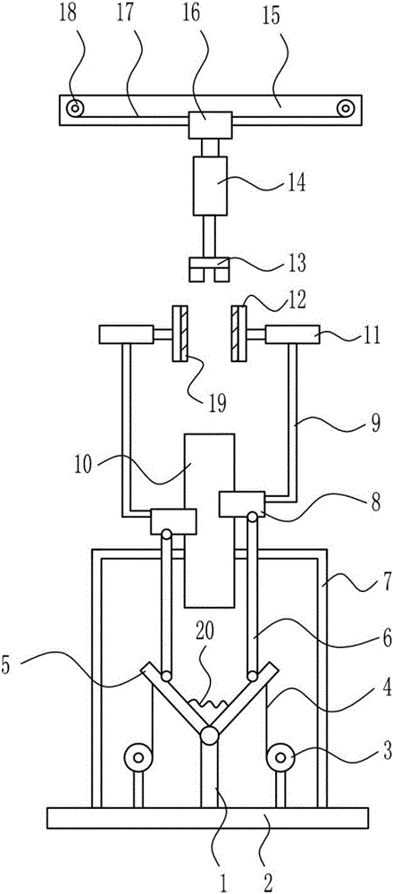
[0034] A carving knife sharpening device for root carving, such as figure 1 As shown, it includes a fixed rod 1, a base 2, a first electric wheel 3, a first wire rope 4, a swing rod 5, a moving rod 6, an L-shaped bracket 7, a first slider 8, a pole 9, and a first slide rail. 10. Electric push rod 11, fixed plate 12, thumb cylinder 13, first cylinder 14, second slide rail 15, second slider 16, second wire rope 17, second electric wheel 18, grindstone 19 and first spring 20. A fixed rod 1 is provided in the middle of the top of the base 2. A swing rod 5 is rotatably connected to the left and right sides of the upper end of the fixed rod 1. The first spring 20 is arranged between the swing rods 5. The left and right sides of the fixed rod 1 are symmetrically provided with a second spring. An electric wheel 3, the first electric wheel 3 is located at the top of the base 2, the first electric wheel 3 is wound with a first steel wire rope 4, the upper ends of the steel wire ropes on...
Embodiment 2
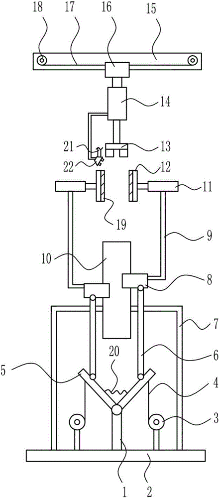
[0036] A carving knife sharpening device for root carving, such as figure 2 As shown, it includes a fixed rod 1, a base 2, a first electric wheel 3, a first wire rope 4, a swing rod 5, a moving rod 6, an L-shaped bracket 7, a first slider 8, a pole 9, and a first slide rail. 10. Electric push rod 11, fixed plate 12, thumb cylinder 13, first cylinder 14, second slide rail 15, second slider 16, second wire rope 17, second electric wheel 18, grindstone 19 and first spring 20. A fixed rod 1 is provided in the middle of the top of the base 2. A swing rod 5 is rotatably connected to the left and right sides of the upper end of the fixed rod 1. The first spring 20 is arranged between the swing rods 5. The left and right sides of the fixed rod 1 are symmetrically provided with a second spring. An electric wheel 3, the first electric wheel 3 is located at the top of the base 2, the first electric wheel 3 is wound with a first steel wire rope 4, the upper ends of the steel wire ropes o...
Embodiment 3
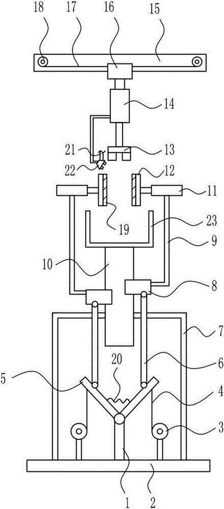
[0039] A carving knife sharpening device for root carving, such as image 3 As shown, it includes a fixed rod 1, a base 2, a first electric wheel 3, a first wire rope 4, a swing rod 5, a moving rod 6, an L-shaped bracket 7, a first slider 8, a pole 9, and a first slide rail. 10. Electric push rod 11, fixed plate 12, thumb cylinder 13, first cylinder 14, second slide rail 15, second slider 16, second wire rope 17, second electric wheel 18, grindstone 19 and first spring 20. A fixed rod 1 is provided in the middle of the top of the base 2. A swing rod 5 is rotatably connected to the left and right sides of the upper end of the fixed rod 1. The first spring 20 is arranged between the swing rods 5. The left and right sides of the fixed rod 1 are symmetrically provided with a second spring. An electric wheel 3, the first electric wheel 3 is located at the top of the base 2, the first electric wheel 3 is wound with a first steel wire rope 4, the upper ends of the steel wire ropes on...
PUM
| Property | Measurement | Unit |
|---|---|---|
| height | aaaaa | aaaaa |
| height | aaaaa | aaaaa |
Abstract
Description
Claims
Application Information