Anti-theft device of vehicle

An anti-theft device and vehicle technology, which is applied to vehicle parts, anti-theft vehicle accessories, transportation and packaging, etc., can solve the problems of illegal removal of GPS antennas by customers, unusable vehicles to supervise payment, etc., and achieve the effect of improving security.

Inactive Publication Date: 2016-12-28
MIKUNI CORP
View PDF1 Cites 0 Cited by
  • Summary
  • Abstract
  • Description
  • Claims
  • Application Information

AI Technical Summary

Problems solved by technology

The purpose of the technology of this patent document 1 is to prohibit the engine start of the subject vehicle in arrears of mortgage payment or rent, thereby making the vehicle unusable and prompting payment
[0003] As a measure to deal with the situation where customers who are in arrears take their vehicles away without permission, a GPS device is installed on the vehicle so that the mortgage company can track the vehicle, but sometimes, for example, the GPS antenna is illegally removed by the customer.

Method used


Image

  • Anti-theft device of vehicle
  • Anti-theft device of vehicle
  • Anti-theft device of vehicle

Examples


Embodiment approach 1

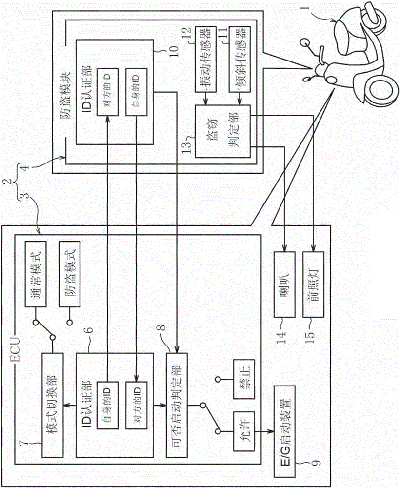
[0048] figure 1 It is an overall configuration diagram showing the motorcycle antitheft device according to the first embodiment.

[0049] The anti-theft device 2 of the motorcycle 1 of the present embodiment is basically made up of ECU3 (engine control unit, engine start determination unit) and anti-theft module 4 (anti-theft control unit, engine start determination unit). It is related to the running function of the motorcycle 1 as in the control of the motorcycle 1, so it is equipped as standard on the vehicle 1.

[0050] In this regard, the anti-theft module 4 is a device specially used for anti-theft, so it is optional. Only users who want the anti-theft function will choose the anti-theft module 4 independently when purchasing the motorcycle 1 . In addition, although the user who does not need the anti-theft function purchases the motorcycle 1 without the anti-theft module 4, if he wants to obtain the anti-theft function during use, he can also purchase the anti-theft m...

Embodiment approach 2

[0078] Next, Embodiment 2 which actualizes this invention as the antitheft device 2 which cooperates with the antitheft management center 21 is demonstrated.

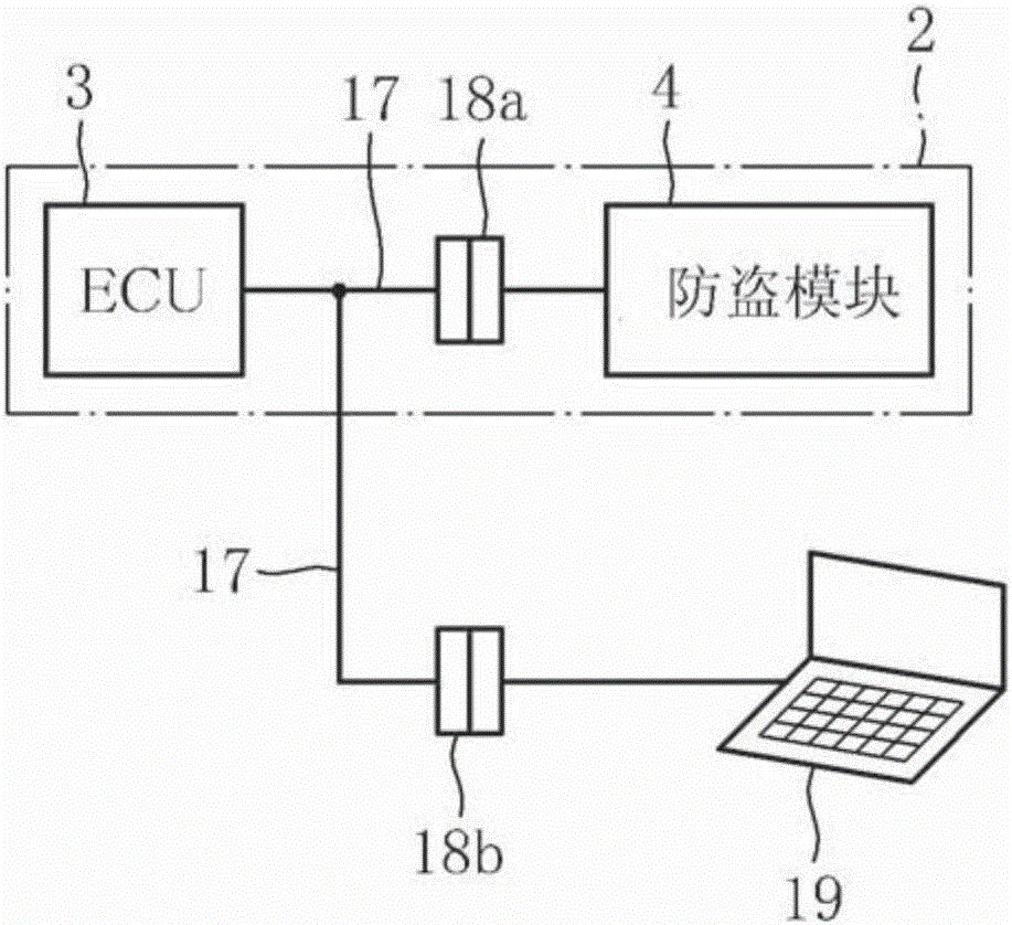
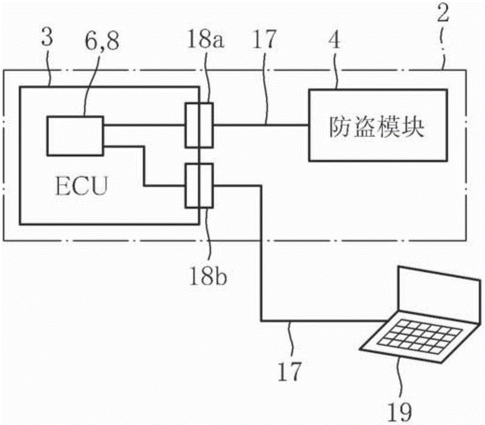
[0079] Figure 5 is an overall configuration diagram showing the antitheft device 2 of the motorcycle 1 according to Embodiment 2, Figure 6 It is an explanatory diagram showing the connection state of the anti-theft module 4 to the ECU 3 via the K-Line 17 .

[0080] The mutual authentication of mutual IDs between the ECU 3 and the anti-theft module 4 is the same as in the first embodiment, but the main difference is that the vehicle 1 user cooperates with the anti-theft management center 21 to deal with vehicle theft and the like.

[0081] First, if based on Figure 5 Now, the structure of the vehicle 1 side will be described. The ID authentication unit 6 and the start-up judgment unit 8 of the ECU 3 have the same structure as that of the first embodiment. And the anti-theft mode switching command from the anti-thef...

Embodiment approach 3

[0132] Next, Embodiment 3 which actualized this invention as another antitheft device 2 which cooperates with the antitheft management center 21 is demonstrated.

[0133] Figure 8 It is an overall configuration diagram showing the antitheft device 2 of the motorcycle 1 according to the third embodiment.

[0134] The point of cooperation with the anti-theft management center 21 is the same as that of the second embodiment, but the main difference is that ID authentication between the ECU 3 and the anti-theft module 4 is performed at the anti-theft management center 21 side when the engine is started. Therefore, the description of the points that are the same as those in Embodiment 2 will be omitted, and the description will focus on the points that are different.

[0135] By transferring the ID authentication function from the ECU3 and the anti-theft module 4 side to the anti-theft management center 21 side, the ID registers 27, 28 that do not have the authentication function...


PUM


Abstract

An anti-theft device of the vehicle according to the invention registers by correlating mutual IDs with respective ID authentication units (6, 10) when an ECU (3) for engine control is electrically connected to an anti-theft module (4) responsible for anti-theft at the beginning. Then, every time the engine starts, mutual IDs of both sides are authenticated between the ECU (3) and the ID authentication units (6, 10) of the anti-theft module (4), the engine is allowed to start under the condition that the mutual IDs are consistent. In a case where the ID of either side is inconsistent or the IDs of the two sides are inconsistent, the illegal replacement of the ECU (3) or the anti-theft module (4) is deemed, and the engine is prohibited to start.

Description

technical field [0001] The present invention relates to an anti-theft device for a vehicle. Specifically, it relates to a method for preventing theft when dismantling or illegally replacing a control device responsible for vehicle engine control and preventive functions, or cutting off electrical wiring (hereinafter these acts are collectively referred to as illegal replacement). An anti-theft device that prohibits engine start for vehicle theft. Background technique [0002] As such a technique for prohibiting engine startup for the purpose of preventing theft, there is a technique described in Patent Document 1, for example. The purpose of the technology of this patent document 1 is to prohibit the start of the engine of the subject vehicle whose mortgage payment or rent is in arrears, thereby making the vehicle unusable and prompting payment. [0003] As a measure against customers who default on payment and take their vehicles away without authorization, GPS devices are...

Claims


Application Information

Patent Timeline
Patent Type & Authority Applications(China)
IPC IPC(8): B60R25/04B60R25/24
CPCB60R25/04B60R25/24B60R2325/306
Inventor 辻一郎高桥晃三浦麿
Owner MIKUNI CORP
Why Eureka
Try Eureka