Quantitative and alarm type bearing lathe with automatic arranging mechanism

An automatic arrangement and lathe technology, applied in turning equipment, toolholder accessories, metal processing, etc., can solve the problems of threading work troubles, reduce bearing quality, and high labor costs, so as to save time and labor, improve quality, The effect of reducing labor costs

CN106392107AInactive Publication Date: 2017-02-15贵州丰达轴承有限公司
0 Cites 1 Cited by

Patent Information

Authority / Receiving Office
CN · China
Patent Type
Applications(China)
Current Assignee / Owner
Publication Date
2017-02-15
Estimated Expiration
Not applicable · inactive patent

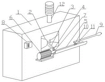
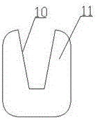
Smart Images

  • Figure 1
    Figure 1
  • Figure 2
    Figure 2
Patent Text Reader

Abstract

The invention discloses a quantitative and alarm type bearing lathe with an automatic arranging mechanism. The quantitative and alarm type bearing lathe comprises a lathe box, wherein an alarm is arranged on the lathe box; a lathe chuck is arranged in the lathe box; a material dropping slot is formed below the lathe chuck; a discharge slot is formed in one side of a discharge end of the material dropping slot; one end of the discharge slot is equipped with an electric telescopic pole; the telescopic end of the electric telescopic pole is equipped with a pushing head; the upper end surface of the pushing head is higher than the lower end surface of the discharge end; a pressure inductor is arranged at one side, close to the discharge slot, of the pushing head; a limiting baffle plate is arranged in a slot in the other end of the discharge slot; a pressure sensor is arranged at one side, opposite to the pushing head, of the limiting baffle plate; the limiting baffle plate is upwards equipped with a through slot from the central point; a circular rod is arranged in the through slot; and the pushing head, the pressure inductor on the limiting baffle plate and the electric telescopic pole are connected on a controller. The quantitative and alarm type bearing lathe disclosed by the invention has the characteristic of being high in stringing efficiency, saving time and labor, saving labor cost, being high in bearing quality, being fixed in stringing quantity, being capable of automatically alarming, and being convenient to use.
Need to check novelty before this filing date? Find Prior Art

Description

technical field

[0001] The invention relates to a bearing lathe, in particular to a quantitative and alarm type bearing lathe with an automatic arrangement mechanism. Background technique

[0002] Bearing lathe is the basic equipment in the process of bearing production. It is to prepare bearings after turning the wool according to size. In the mass production workshop of bearings, the processing speed is fast. After the bearings are processed, they will automatically fall from the chuck of the lathe. , In order to facilitate the collection of bearings, the current method is to set a funnel-shaped feeding trough under the chuck, and lead it to a special collection device (usually a box or barrel) through a drainage pipe, before being transported to the next process. , the bearing needs to be coaxially threaded into a string. After the bearing is drained into the collection device, the placement is very chaotic, and the work of stringing is very troublesome. The commonly used...

Examples

Embodiment Construction

[0013] The present invention will be further described below in conjunction with the accompanying drawings and embodiments, but not as a basis for limiting the present invention.

[0014] The embodiment of the present invention: a quantitative and alarm type bearing lathe with an automatic arrangement mechanism, as shown in the appendix Figure 1-2 As shown, it includes a lathe box 1, an alarm 12 is arranged on the lathe box 1, a lathe chuck 2 is arranged in the lathe box 1, and a discharging chute 3 is arranged under the lathe chuck 2, and the discharging chute 3 The end 4 passes through the lathe box 1, and a discharge chute 5 perpendicular to the discharge chute 3 and horizontal is provided on one side of the discharge end 4. One end of the discharge chute 5 is provided with an electric telescopic rod 6, and the electric telescopic rod 6 The telescopic end of the pusher head 7 is provided with a pusher 7, the upper end face of the pusher head 7 is higher than the lower end ...