Scanning mirror and scanning method thereof

A technology for scanning mirrors and mirrors, which is applied in the field of mirrors, can solve the problems of high cost, complex structure, difficulty in meeting the scanning frequency, etc., and achieve the effect of large scanning angle

Active Publication Date: 2017-03-22
深圳市微觉未来科技有限公司
View PDF6 Cites 4 Cited by
  • Summary
  • Abstract
  • Description
  • Claims
  • Application Information

AI Technical Summary

Problems solved by technology

However, the expansion space of the multi-line 2D scanning mode is too small, and increasing the vertical resolution is equivalent to increasing the thread, and the increase of the thread will make the structure more complicated and the cost higher
In contrast, although the current one-dimensional scanning mirror technology is not mature enough to achieve longitudinal scanning, it has a large space for expansion, and the increase in the scanning frequency of the one-dimensional scanning mirror can significantly increase the vertical resolution.
However, the current mainstream one-dimensional laser scanners are difficult to meet their needs.
[0003] At present, the mainstream one-dimensional laser scanners include piezoelectric ceramic scanners, voice coil motor scanners and MEMS scanners. Among them, the optical scanning angle of piezoelectric ceramic scanners is usually very small, and it is difficult to meet the optical scanning of plus or minus 10 degrees; In addition, the scanning frequency of the voice coil motor scanner is small, and it is difficult to meet the scanning frequency above 300 Hz; and it is difficult for the scanner in the prior art to work under a fixed scanning amplitude and frequency.

Method used


Image

  • Scanning mirror and scanning method thereof
  • Scanning mirror and scanning method thereof
  • Scanning mirror and scanning method thereof

Examples


Embodiment 1

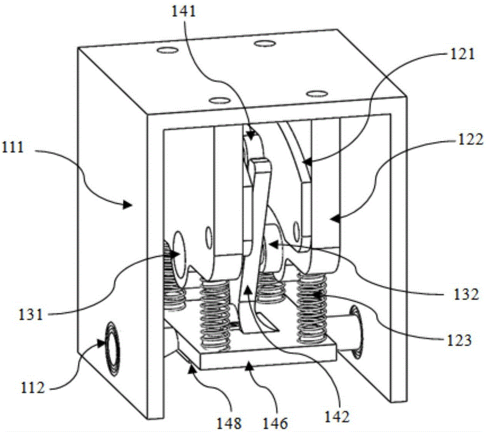
[0043] see Figure 1-2 . As shown in the figure, the present invention discloses a scanning mirror, including a laser reflection module 140 and a laser feedback module 130; the laser reflection module 140 is used to reflect laser light; Feedback compensation of amplitude and frequency enables the scanning mirror to work at a fixed scanning amplitude and a fixed frequency.

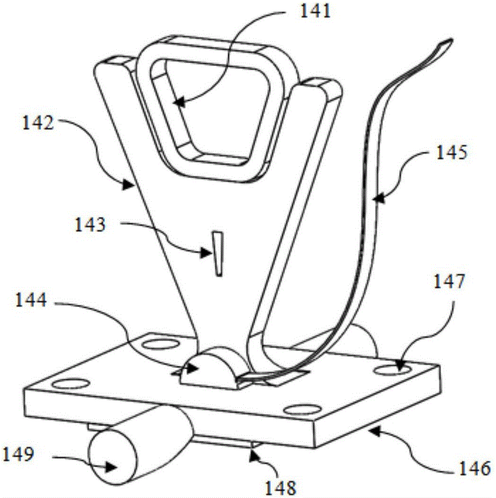
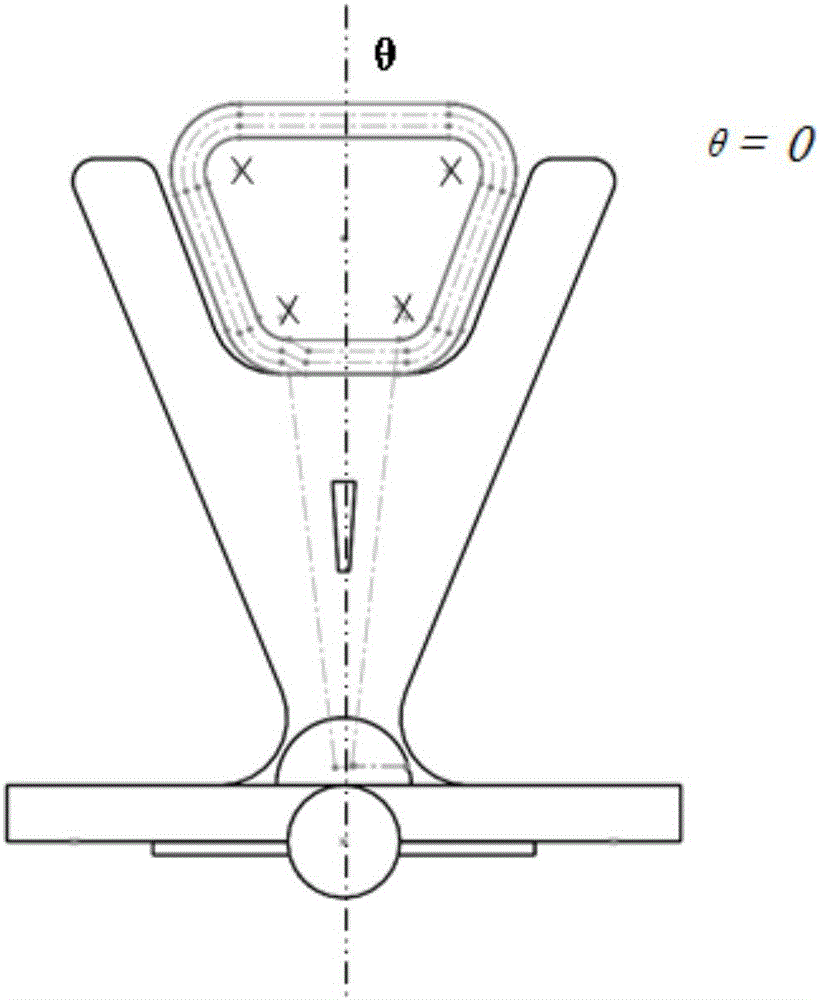
[0044] The laser reflection module 140 includes a coil 141, a base 146, a rotating shaft 149 and a mirror 148. The coil 141 is fixed on the upper surface of the base 146 through a coil bracket 142, and the mirror 148 is bonded to the The lower surface of the base 146, the lens thickness of the reflector 148 is 1mm, the mirror surface of the reflector 148 is rectangular, and the mirror surface size is 10mm * 10mm; the two sides of the base 146 are provided with a rotating shaft 149, The rotation axis 149 is perpendicular to the plane where the coil 141 is located, and the reflector 148 deflects around the ...

Embodiment 2

[0066] The invention discloses a scanning mirror, which includes a laser reflection module 140 and a laser feedback module 130; the laser reflection module 140 is used to reflect infrared laser; the laser feedback module 130 controls the amplitude and frequency of the scanning mirror Feedback compensation enables the scanning mirror to work at a fixed scanning amplitude and a fixed frequency.

[0067] The laser reflection module 140 includes a coil 141, a base 146, a rotating shaft 149 and a mirror 148. The coil 141 is fixed on the upper surface of the base 146 through a coil bracket 142, and the mirror 148 is bonded to the The lower surface of the base 146, the lens thickness of the reflector 148 is 1mm, the mirror surface of the reflector 148 is circular, and the mirror diameter is 10mm; The rotation axis 149 is perpendicular to the plane where the coil 141 is located, and the reflector 148 deflects around the rotation axis 149 when the coil 141 is energized.

[0068] The m...


PUM


Abstract

The invention discloses a scanning mirror which comprises a laser reflection module and a laser feedback module. The laser reflection module is used for reflecting laser. The laser feedback module enables the scanning mirror to operate at a fixed scanning amplitude and a fixed frequency through feedback compensation of the amplitude and frequency of the scanning mirror. The invention further discloses a scanning method of the scanning mirror. According to the invention, the scanning mirror has a large scanning angle, and can realize optical scanning of plus or minus 15 degrees; the scanning frequency is greater than 300 Hz; the mirror size of the scanning mirror is equal to or greater than 10mm*10mm; and the scanning mirror can operate at the fixed scanning amplitude and the fixed frequency.

Description

technical field [0001] The invention relates to the field of mirrors, in particular to a scanning mirror and a scanning method thereof. Background technique [0002] When expanding from 2D lidar to 3D lidar, it is necessary to increase the number of scanning points in the vertical direction. There are two mainstream methods: using multi-line 2D scanning mirrors to realize longitudinal scanning and using one-dimensional scanning mirrors to realize longitudinal scanning. However, the expansion space of the multi-line 2D scanning mode is too small, and increasing the vertical resolution is equivalent to increasing the thread, and the increase of the thread will make the structure more complicated and the cost higher. In contrast, although the currently used one-dimensional scanning mirror is not mature enough to realize longitudinal scanning, it has a large space for expansion, and the increase in the scanning frequency of the one-dimensional scanning mirror can significantly i...

Claims


Application Information

Patent Timeline
Patent Type & Authority Applications(China)
IPC IPC(8): G02B26/10
CPCG02B26/101
Inventor 罗栋熊小刚陈四海李鹏郑富瑜梁增基
Owner 深圳市微觉未来科技有限公司
Why Eureka
Try Eureka