Frequency scanning reflecting grating antenna and mirror reflecting wave restraining method thereof

A technology of frequency scanning and reflective grating, applied in the terahertz field, can solve the problems of time-consuming, imaging time up to several seconds, and shortened scanning time, and achieve low direct reflection sidelobes, wide scanning range, and large scanning angle Effect

Active Publication Date: 2015-06-10
INST OF ELECTRONICS CHINESE ACAD OF SCI
View PDF1 Cites 4 Cited by
  • Summary
  • Abstract
  • Description
  • Claims
  • Application Information

AI Technical Summary

Problems solved by technology

The terahertz imaging principle prototype has been developed now, such as the 0.345THz-0.355THz scanning 3D imaging system developed by the US PNL laboratory in 2009, and the 0.66THz-0.69THz frequency-modulated continuous wave 3D imaging system developed by the US JPL laboratory in 2011 These systems use the rotation of one or more reflective surfaces to realize two-dimensional beam scanning, and the imaging time is as long as several seconds, which is extremely time-consuming in practical applications
Since frequency scanning means that different frequencies correspond to beams of different directions in space, the scanning time will be greatly shortened. Therefore, it is very promising to use frequency scanning to realize beam scanning, but no one has yet realized the terahertz frequency band. frequency scanning antenna

Method used


Image

  • Frequency scanning reflecting grating antenna and mirror reflecting wave restraining method thereof
  • Frequency scanning reflecting grating antenna and mirror reflecting wave restraining method thereof
  • Frequency scanning reflecting grating antenna and mirror reflecting wave restraining method thereof

Examples


specific Embodiment approach

[0030] The specific implementation method is as follows 7 steps:

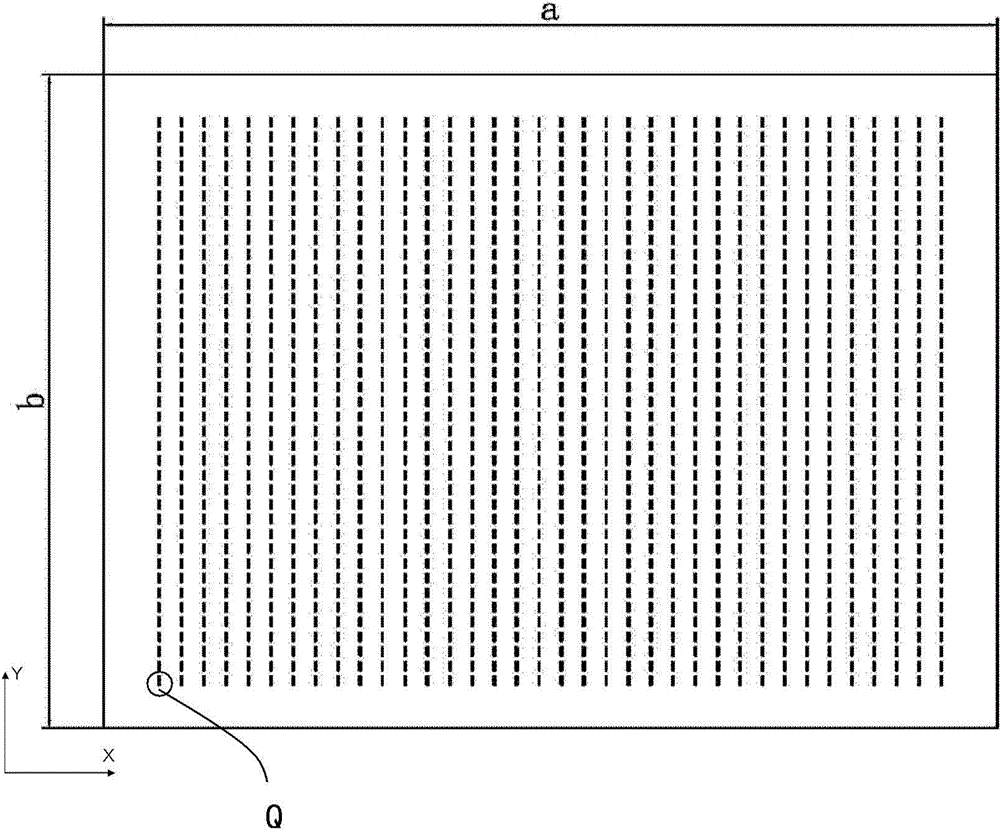
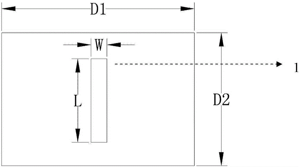
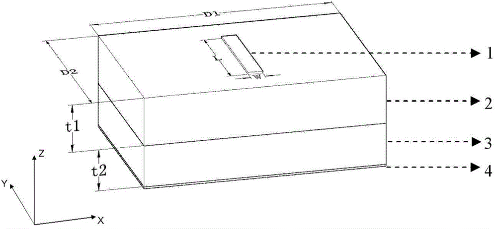
[0031] Step 1: According to the required scanning angle and the set incident angle, pass the grating equation D 1 (sinθ 0 +sinθ -1 )=λ, calculate the period of the metal grid strip 1 in the x direction, where D1 is the period of the reflection unit in the x direction, θ 0 is the incident angle of the incident beam, θ -1 is the scanning angle of the scanning diffracted beam, λ is the wavelength of the electromagnetic wave; the cycle selection in the x direction should meet the requirement that no other high-order modes appear except for the -1-order high-order mode, and the period D 1 To meet:

[0032] λ 1 + | sin θ 0 | D 1 min ( 2 ...


PUM


Abstract

The invention relates to a frequency scanning reflecting grating antenna. The frequency scanning reflecting grating antenna comprises a plurality of reflecting units, wherein the reflecting units are arrayed periodically in a two-dimensional manner; each reflecting unit comprises metal grid bars, a top layer, a bottom layer and a metal bottom plate; each metal bottom plate is arranged on the bottom of the corresponding reflecting unit; the top of each reflecting unit is provided with the corresponding metal grid bars; each top layer and the corresponding bottom layer are fixedly connected between the corresponding metal grid bars and the corresponding metal bottom plate; the bottoms of the metal grid bars of each reflecting unit are fixedly connected to the top of the corresponding top layer; each bottom layer is fixedly connected between the bottom of the corresponding top layer and the top of the corresponding metal bottom plate; each top layer and the corresponding bottom layer are multi-media layers with different dielectric constants; and the multi-media layers restrain mirror reflecting waves. The antenna can be used for scanning in a large-angle range of a frequency band nearby 0.2THz, and has properties of high gain and low mirror reflecting minor lobe. The invention also provides a mirror reflecting wave restraining method.

Description

technical field [0001] The invention belongs to the technical field of terahertz, and relates to a frequency-scanning reflective grating antenna based on a multilayer medium. By designing the multi-layer dielectric structure of the antenna base, this antenna can suppress the direct reflection wave. The antenna has a large gain, a wide scanning range, and low direct reflection sidelobes. It can be used for terahertz imaging, fast target detection and tracking, terahertz communication, non-destructive testing, etc. Background technique [0002] Terahertz waves generally refer to electromagnetic waves with a frequency between 0.1THz and 10THz. It is the frequency band least studied and used by people. It has attracted great attention in the past ten years. Since the frequency band is located between microwave and infrared spectrum, it belongs to the transition range from macroscopic electronics to microscopic electronics. Terahertz waves exhibit characteristics different from...

Claims


Application Information

Patent Timeline
Patent Type & Authority Applications(China)
IPC IPC(8): H01Q15/14
Inventor 李世超李超张晓娟方广有
Owner INST OF ELECTRONICS CHINESE ACAD OF SCI
Why Eureka
Try Eureka