High-speed optical scanning display device

An optical scanning, high-speed technology, applied in the field of optical information display, can solve the problems of small scanning angle, noise, control, lubrication, cost and life, etc., and achieve large scanning angle, high working stability and high scanning accuracy Effect

Inactive Publication Date: 2014-03-19
JILIN UNIV
View PDF4 Cites 2 Cited by
  • Summary
  • Abstract
  • Description
  • Claims
  • Application Information

AI Technical Summary

Problems solved by technology

For example, the high-definition screen has 1080 lines, the refresh rate is 50 times / second, and it needs to scan 54,000 times per second. When using an octagonal prism wheel, it can scan 8 times because of one rotation, so 54,000 times / 8 is 6750 revolutions / second. The rotation speed of the prism wheel is 405,000 rpm. The noise, control, lubrication, cost and life caused by such a high rotation speed are difficult to meet the practical conditions for the market
Another way to deflect the laser beam is acousto-optic scanning. Compared with the previous method, acousto-optic scanning uses the effect of ultrasonic waves on light to deflect the beam to achieve scanning. Since there is no large-scale mechanical movement, it has It has the advantages of easy control, fast scanning speed, and simple system structure, but its disadvantage is that the scanning angle is small

Method used


Image

  • High-speed optical scanning display device
  • High-speed optical scanning display device
  • High-speed optical scanning display device

Examples


Embodiment 1

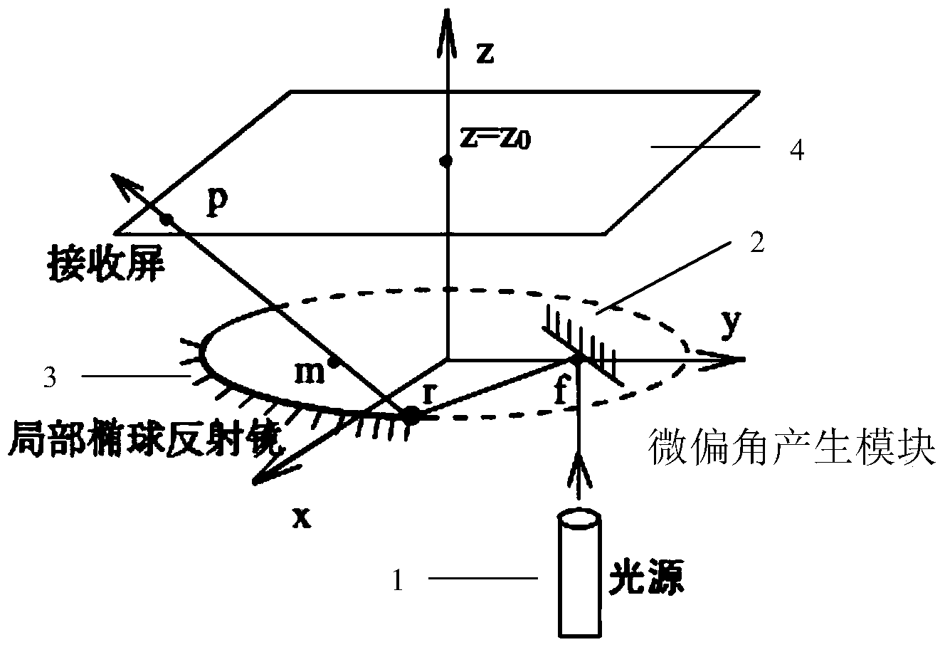
[0021] refer to figure 1 A high-speed optical scanning display device includes a light source 1 , a micro-deflection angle generating module 2 , a partial ellipsoid mirror 3 and a receiving screen 4 sequentially placed along the optical path. The micro-deflection angle generation module 2 is composed of a mirror element and a control device that can change the orientation of the mirror surface. The mirror element is a square plane mirror with a side length of 1um-1dm, and the center of the mirror element is at the distance of the ellipsoid The partial ellipsoid mirror 3 is on the far focus point, and can rotate around the center of the mirror element in two degrees of freedom under the drive of the control device.

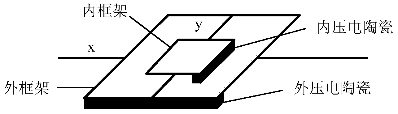
[0022] The structure of described control device sees figure 2 , the device has a structure similar to a gimbal, in which one end of the outer frame is connected to the outer piezoelectric ceramic stack, and can rotate around the central axis x-axis of the outer ...

Embodiment 2

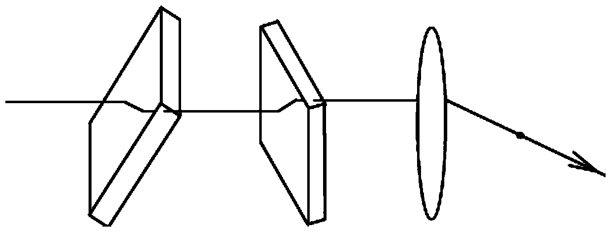
[0025] refer to image 3 , the micro-deflection angle generation module 2 in embodiment 1 is replaced by image 3 The structure shown in , that is, the micro-deflection angle generating module 2 is composed of two transparent plates with controllable refractive index, a refractive index adjusting device and a convex lens. The transparent plate with controllable refractive index is a structure in which two parallel transparent electrodes sandwich a liquid crystal or an electro-optic crystal. Since the refractive index of liquid crystals or electro-optic crystals changes with the voltage applied to them, the refractive index can be controlled by changing the voltage between the electrodes. After the light passes through the first transparent plate, a slight translation occurs in the paper surface, and after the light passes through the second transparent plate, a slight translation occurs in the plane perpendicular to the paper surface. The magnitude of the two translations is ...

Embodiment 3

[0027] refer to Figure 4 The same purpose can also be achieved by replacing the convex lens in the micro-deflection angle generating module 2 in Embodiment 2 with a parabolic mirror coated with a reflective film inside.


PUM

PropertyMeasurementUnit
eccentricityaaaaaaaaaa

Abstract

The invention, which belongs to the technical field of optical displaying, provides a high-speed optical scanning display device. The structure of the device is characterized in that the device comprises a light source (1) a micro drift angle generation module (2), a local ellipsoidal reflector (3) and a receiving screen (4), wherein the micro drift angle generation module (2), the local ellipsoidal reflector (3) and the receiving screen (4) are successively arranged along an optical path. The micro drift angle generation module (2) enables a micro drift angle of light to occur; the local ellipsoidal reflector (3) is used for amplifying the drift angle; and then a light spot for scanning with a control signal is formed at the receiving screen (4) so that image displaying is realized. According to the invention, problems of poor precision and difficult stability control of optical machine scanning as well as a small scanning angle of acousto-optic scanning can be solved. The display device has the characteristics of high scanning precision and high stability; and the micro angle change of the light can be amplified to 1 to 4 magnitude orders.

Description

technical field [0001] The invention belongs to the technical field of optical information display, in particular to a device that can be used for high-speed optical scanning display. Background technique [0002] Compared with traditional TV, laser TV has many advantages: vivid color, high brightness, flexible screen size, etc. Laser display has low environmental requirements, usually does not need any optical focusing system, and the display size can be adjusted arbitrarily, which can be developed into a multi-functional product integrating super large screen display, movie projection. However, due to technical bottlenecks, laser TV has not been commercialized. [0003] In terms of technology, scanning deflection in laser TV is a difficult problem: like CRT color picture tube, the laser beam has to scan the entire image line by line from top to bottom. The main way to deflect the laser beam is to irradiate the laser beam on the high-speed rotating multi-faceted prism whe...

Claims


Application Information

Patent Timeline
Patent Type & Authority Applications(China)
IPC IPC(8): G02B26/10G02F1/13G02F1/03
Inventor 王广军吴香英龙国徽纪媛庞明俊
Owner JILIN UNIV
Why Eureka
Try Eureka