
Rotary three-dimensional foot shape and plantar pressure scanner and working method thereof

A plantar pressure and scanner technology, which is applied to instruments, foot or shoe last measuring devices, clothing, etc., to promote industrial upgrading, improve sports biomechanics research level, and promote development

Active Publication Date: 2019-05-03
HEFEI INSTITUTES OF PHYSICAL SCIENCE - CHINESE ACAD OF SCI
View PDF6 Cites 12 Cited by
  • Summary
  • Abstract
  • Description
  • Claims
  • Application Information

AI Technical Summary

Problems solved by technology

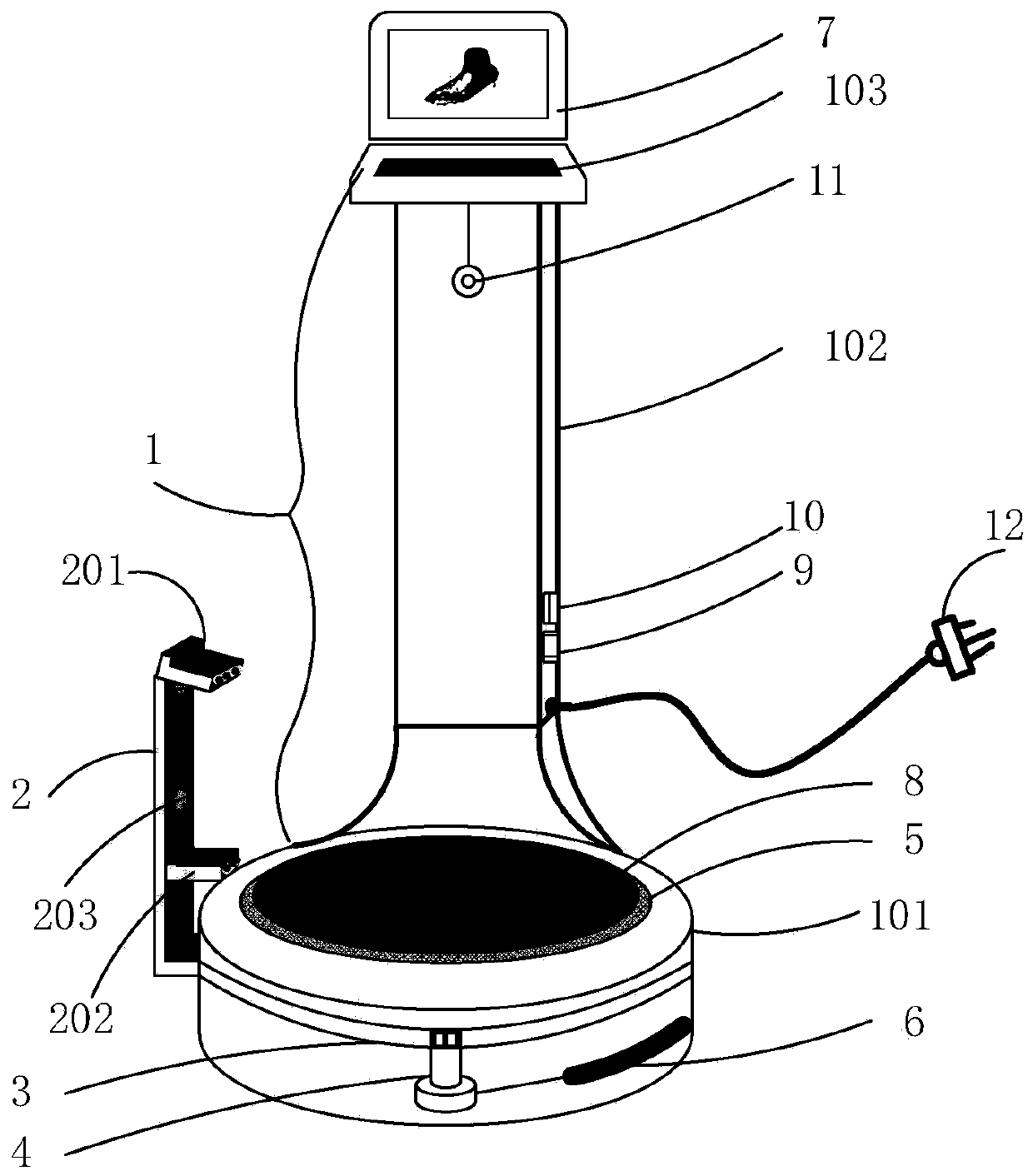
[0005] In order to solve the problems of using three or more optical scanners in the prior art, such as high cost, no plantar pressure distribution measurement function, relatively single output data of the equipment, and unspecific implementation methods, the present invention provides a rotating three-dimensional foot Form and plantar pressure scanner and its working method, solve the technical problem of three-dimensional foot form and plantar pressure distribution integrated rapid scanning measurement

Method used


Image

  • Rotary three-dimensional foot shape and plantar pressure scanner and working method thereof
  • Rotary three-dimensional foot shape and plantar pressure scanner and working method thereof
  • Rotary three-dimensional foot shape and plantar pressure scanner and working method thereof

Examples


Embodiment Construction

[0046] The following will clearly and completely describe the technical solutions in the embodiments of the present invention with reference to the accompanying drawings in the embodiments of the present invention. Obviously, the described embodiments are only some, not all, embodiments of the present invention. Based on the embodiments of the present invention, all other embodiments obtained by persons of ordinary skill in the art without making creative efforts belong to the protection scope of the present invention.

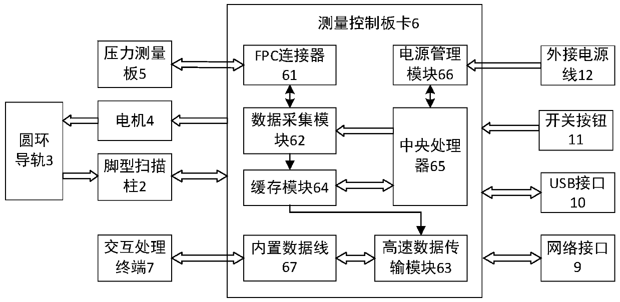
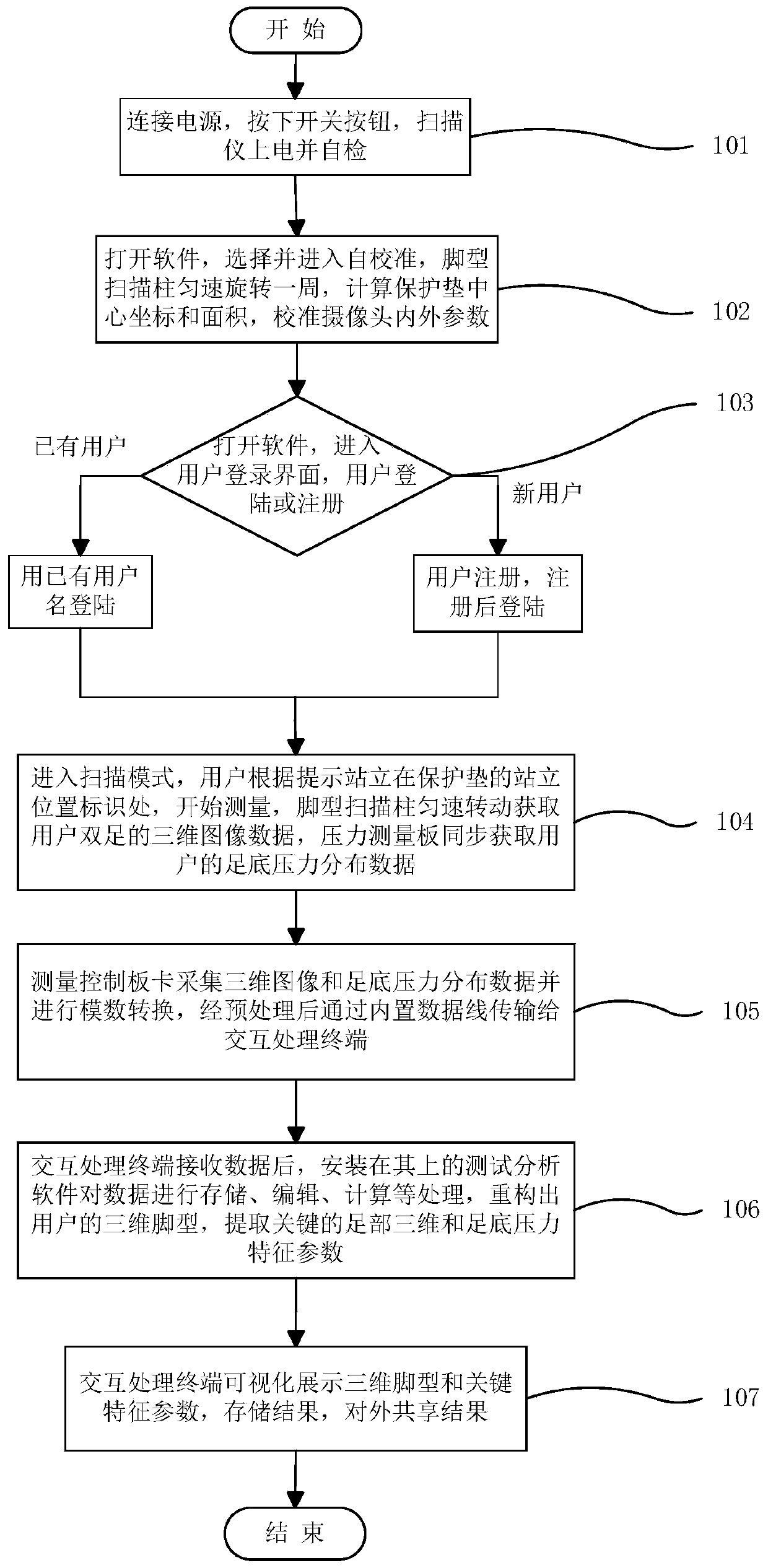
[0047] Such as figure 1 As shown, the rotary three-dimensional foot shape and plantar pressure scanner includes a vertical control platform 1, a foot shape scanning column 2, a circular guide rail 3, a motor 4, a pressure measurement board 5, a measurement control board 6, and an interactive processing terminal 7. Protection pad 8, network interface 9, USB interface 10, switch button 11 and external power cord 12; vertical control platform 1 includes platform ...


PUM


Abstract

The invention provides a rotary three-dimensional foot shape and plantar pressure scanner and a working method thereof. The scanner comprises a vertical control platform, a foot shape scanning column,a circular-ring guide rail, a motor, a pressure measuring board, a measurement control board card, an interaction and processing terminal, a protection pad, a network interface, a USB interface, a switch button and an external power cable. The foot shape scanning column is installed at the outer side of the platform base of the vertical control platform and is fixedly connected with the circular-ring guide rail by a screw. The foot shape scanning column is driven by the motor to make constant-speed circular rotation with the circular-ring guide rail. When the column rotates, an upper 3D real-sensing camera module and a lower 3D real-sensing camera module work cooperatively to obtain three-dimensional image data of feet of the user. The pressure measuring board installed in the center of the platform base is used for acquiring plantar pressure distribution data of the user synchronously; the measurement control board card is responsible for controlling the foot shape scanning column and the pressure measuring board to collect data and transmit the collected data to the interaction and processing terminal. Therefore, the foot morphological and sport dynamics parameters of the user can be obtained synchronously, conveniently and quickly and the analysis is fused; complementary scanning is realized; and self-calibration can be carried out.

Description

technical field [0001] The invention relates to the field of foot digital automatic measurement, in particular to a rotary three-dimensional foot shape and plantar pressure scanner and a working method thereof. Background technique [0002] Three-dimensional foot shape measurement technology is the basic technology in the fields of shoemaking, foot disease diagnosis, treatment and rehabilitation, and foot biomechanical analysis and research. In the early days, manual measurement was often used, which had defects such as high labor intensity, low efficiency, and poor accuracy, and lacked the description of the overall characteristic information of the foot shape. With the development of measurement technology, technical methods such as scanning technology, photo synthesis technology, and mold inversion technology have emerged to improve the measurement efficiency and accuracy; the plantar pressure distribution measurement technology is to use pressure measuring instruments to...

Claims


Application Information

Patent Timeline
IPC IPC(8): G01D21/02A43D1/02
Inventor 姚志明杨先军张晓翟周旭何江南孙怡宁李红军王涛
Owner HEFEI INSTITUTES OF PHYSICAL SCIENCE - CHINESE ACAD OF SCI
Learn More