Training device and method

a technology for monitoring devices and sports, applied in the field of training devices and methods, can solve the problems of reducing the useful heart rate limiting function of the device, unable to achieve the setting of the lower and higher limits of the heart rate, and unable to carry out the resolution to an unusable level, so as to achieve the effect of simplifying the use of the heart rate monitor

Active Publication Date: 2007-01-18
SUUNTO OY
View PDF6 Cites 69 Cited by
  • Summary
  • Abstract
  • Description
  • Claims
  • Application Information

AI Technical Summary

Benefits of technology

[0010] It is an aim of the invention to provide a novel device structure and method that enable simpler use of a heart rate monitor.

Problems solved by technology

If the linear scale of the slide bar is extended, the resolution degrades to an unusable level due to a limited resolution and size of digital displays.
In many prior art devices, setting of the lower and higher limits for heart rate is very difficult to carry out.
The procedure is therefore often left undone in the beginning of an exercise, whereby the useful heart rate limiting function of the device remains unused.
In addition, the prior art solutions related to heart rate monitor displays are such that it is difficult for the user to quickly see the present heart rate and the heart rate limits.
When jogging, for example, the device unavoidably shakes, whereby perceiving of the heart rate with respect to the limits takes a long while.

Method used


Image

  • Training device and method
  • Training device and method
  • Training device and method

Examples


Embodiment Construction

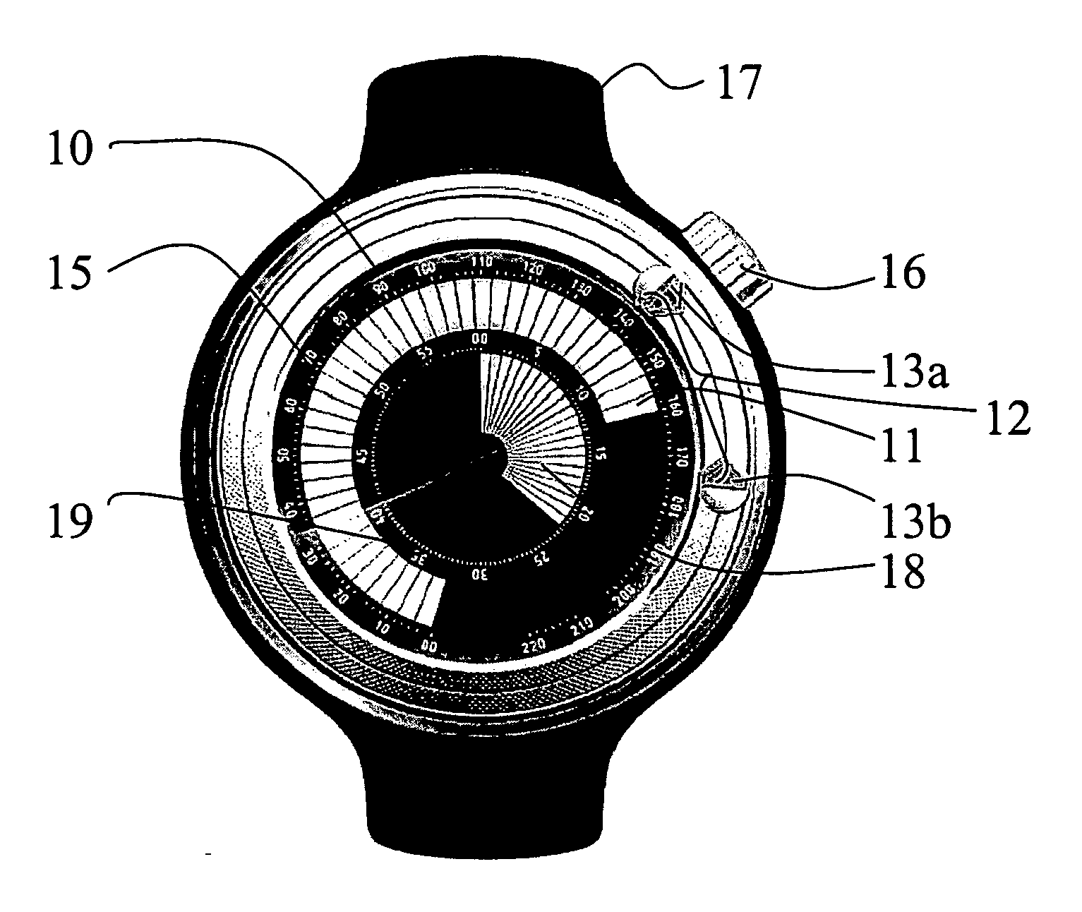
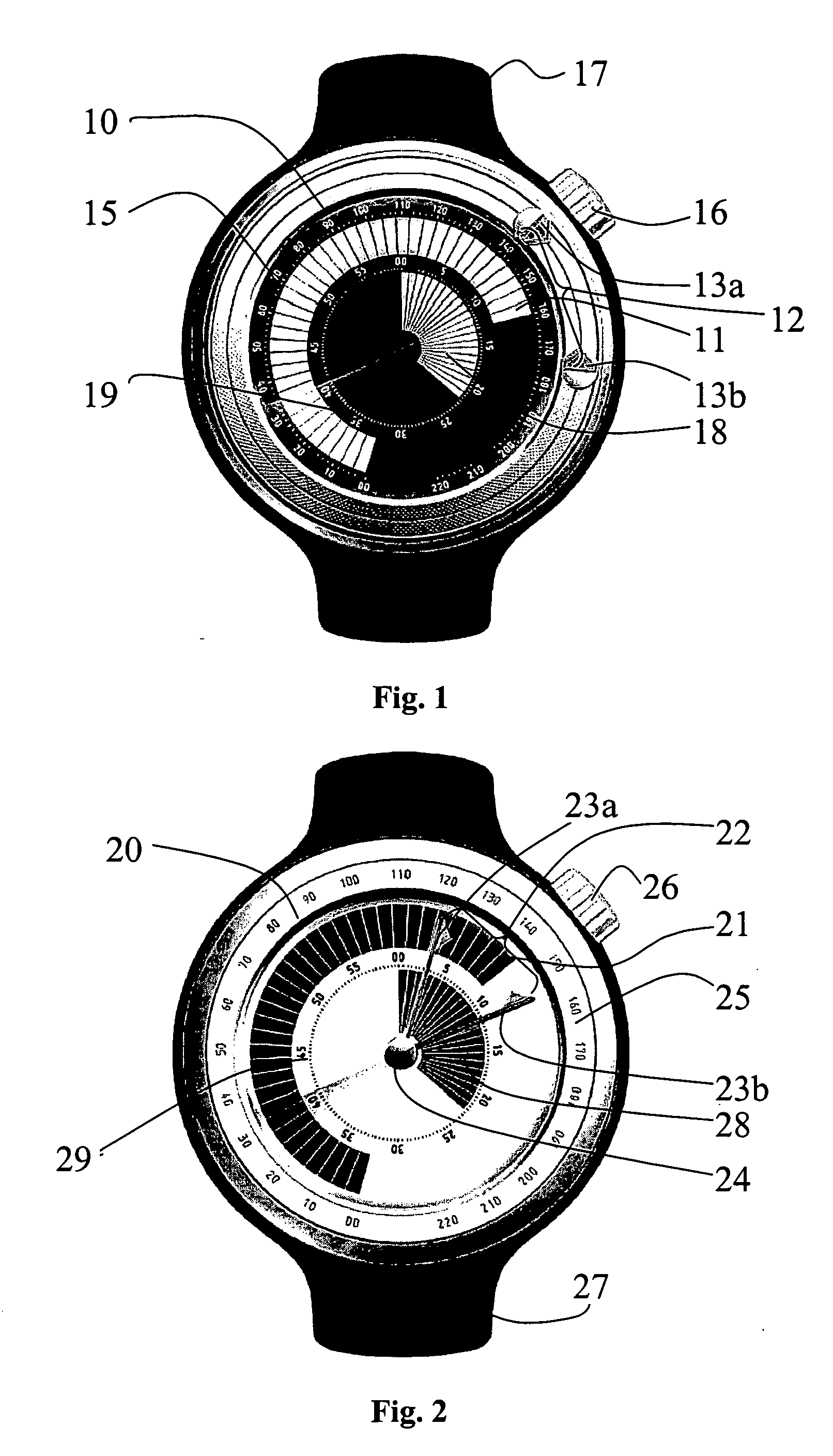
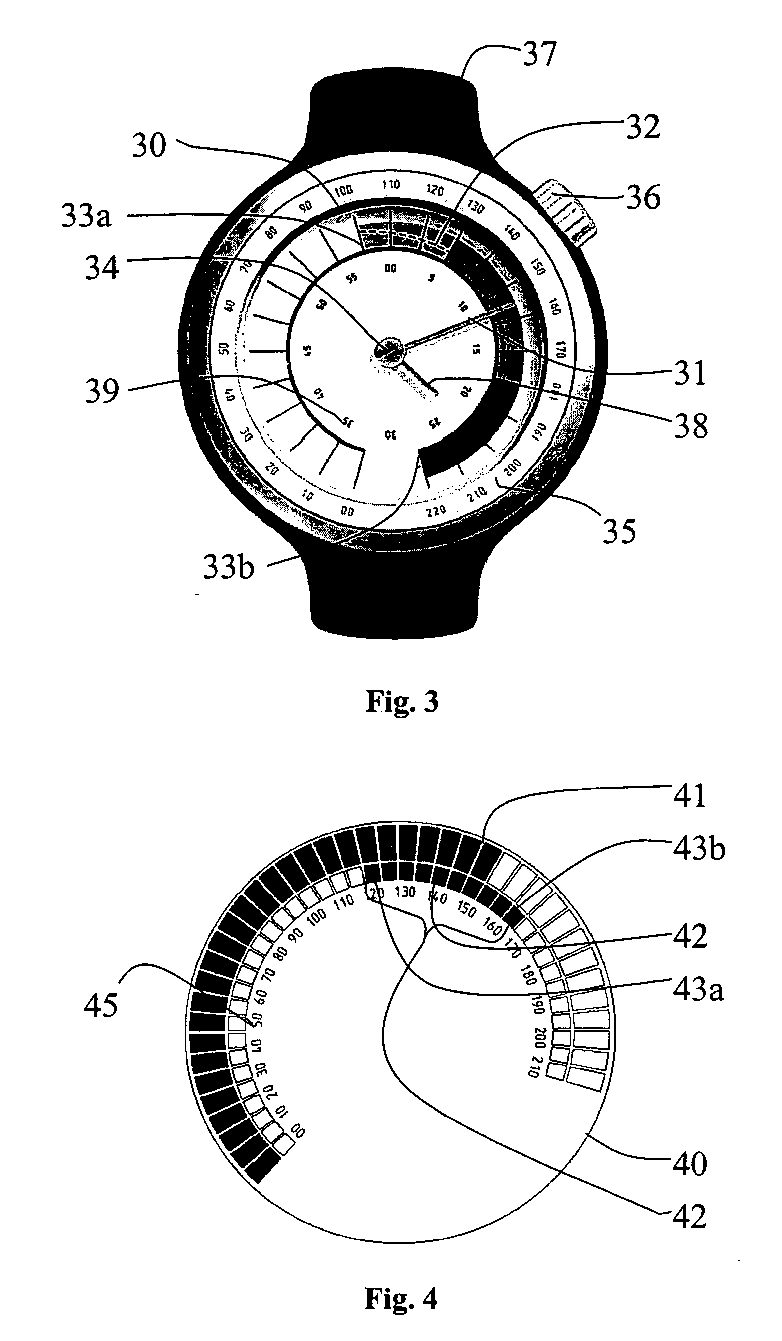
[0035]FIG. 1 shows a first preferred embodiment of a wristop computer according to the invention. The dial of the product is denoted with the reference numeral 10. The current heart rate indicator 11 and the reference indicator are arranged orbicularly in the dial area. The current heart rate indicator 11 is implemented using radially arranged digital display segments, which can be highlighted one after another depending on the current heart rate and the heart rate scale used. The reference indicator comprises a lower level marker 13a and a higher level marker 13b, which define an intervening reference range 12. In this example, the lower and higher level markers 13a, 13b comprise Bezel-mounted physical indicators (knobs) which are rotatable along the fringe of the dial. The lower level indicator can be colored green to indicate “go” and the higher level marker can be colored red to indicate “slow down”, for example. The lower and higher level markers 13a, 13b are preferably individ...


PUM


Abstract

The invention relates to heart rate monitors. The monitor according to the invention comprises a dial, which comprises a current heart rate indicator, which is responsive to a heart rate signal measured from a user of the wristop computer and functionally connected to a heart rate scale, and a reference indicator defining a visually identifiable reference heart rate range. According to the invention, at least one of the indicators is rotatably adjustable relative to the dial, and the heart rate scale and the reference heart rate range are adjustable relative to each other. The invention also concerns a method for monitoring the heart rate of a sportsman. By means of the invention, a quickly perceivable and adjustable heart rate monitor structure can be achieved.

Description

BACKGROUND OF THE INVENTION [0001] 1. Field of the Invention [0002] The invention relates to a performance-monitoring device used in sports. In particular, the invention concerns a wristop device, which can be used for monitoring the intensity of training. Such a device monitors the physiological state of a sportsman and provides training-related data to the sportsman. The invention also concerns a method of carrying out exercise monitoring. [0003] 2. Description of Related Art [0004] EP 1245184 discloses a heart rate monitor having a digital display, which comprises panels for showing a lower and higher limit of the heart rate in numbers. A highlighted section of a slide bar is moved between the higher and lower limit to show the current heart rate of the user of the device. The heart rate is also shown in number format in a corner of the display. The device is restricted to showing in an illustrative way only the heart rates between the lower and upper limits. If no section of the...

Claims


Application Information

Patent Timeline
Patent Type & Authority Applications(United States)
IPC IPC(8): A61B5/04
CPCA63B2071/0663G04G21/025A63B2230/06
Inventor BUTT, PHILLIPAHLSTROM, MIKKOPERNU, KIMMO
Owner SUUNTO OY
Why Eureka
Try Eureka