Nano-Precision Sintering System

a sintering system and nano-precision technology, applied in the field of nano-precision sintering system, can solve the problems of inhibiting the attainment of desired properties, insufficient to produce ultra-purified sintered compacts with ultra-high precision, and simply using the conventionally known pulse energization and pressure sintering apparatus, etc., to achieve high precision and high function

Inactive Publication Date: 2008-07-24
FUJI ELECTRONICS IND
View PDF3 Cites 74 Cited by
  • Summary
  • Abstract
  • Description
  • Claims
  • Application Information

AI Technical Summary

Benefits of technology

[0006]An object of the present invention is to provide a nano-precision sintering system for sintering a nano-sized powder of a starting material to form a sintered compact with ultra high precision and high function having a structure defined by a nano-sized crystal grain diameter.

Problems solved by technology

However, they have also found that suppressing the grain growth simply by using the conventionally known pulse energization and pressure sintering apparatus would be insufficient to produce a highly purified sintered compact with ultra high precision and high function and also having a structure defined by a nano-sized crystal grain diameter by sintering a nano-sized powder of a material containing no impurities.
This is due to a drawback explained by a known fact that the nano-sized powder has a larger specific surface area compared with an ordinary type of powder defined by the micron order and also has a high activity in the grain surface that could form an oxide film easily, when exposed to the atmosphere, which oxide film could be deposited on the grain boundary or dispersed internally during synthesizing of the material, thus inhibiting a desired property from being obtained.

Method used


Image

  • Nano-Precision Sintering System
  • Nano-Precision Sintering System
  • Nano-Precision Sintering System

Examples


Embodiment Construction

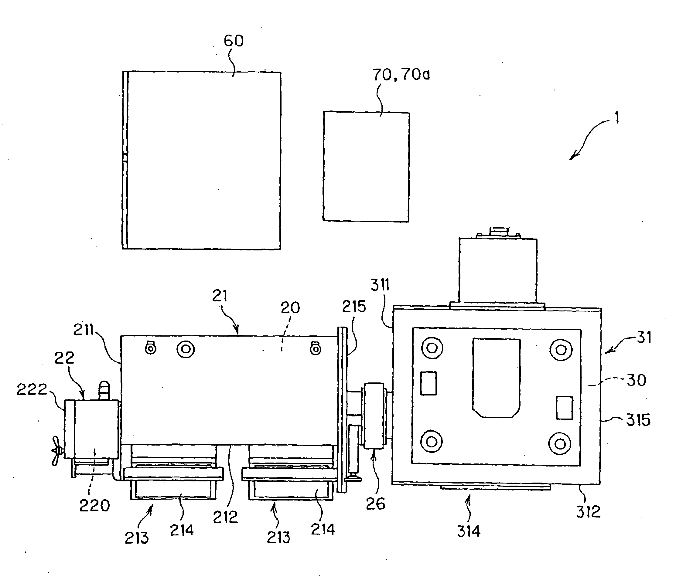
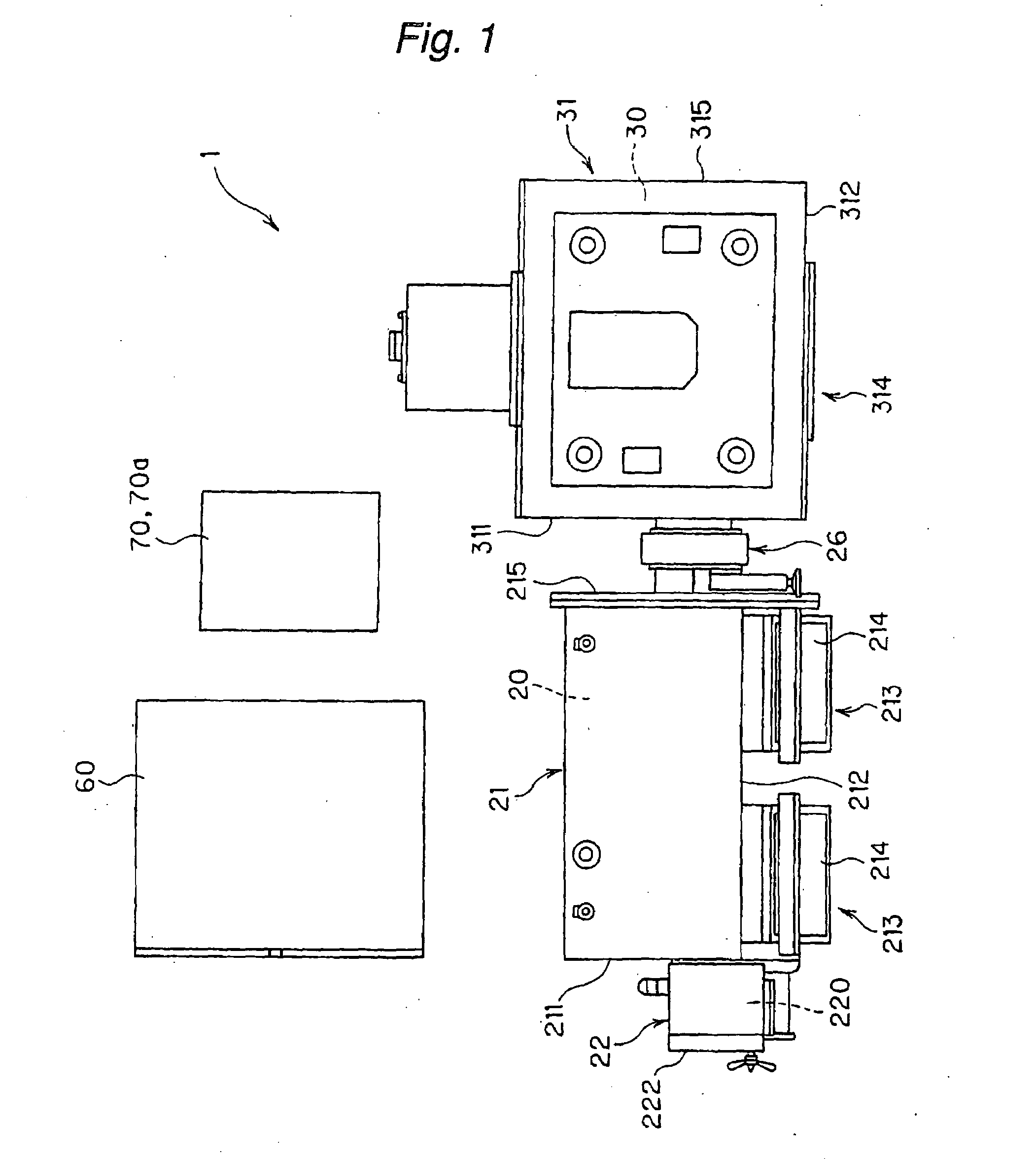
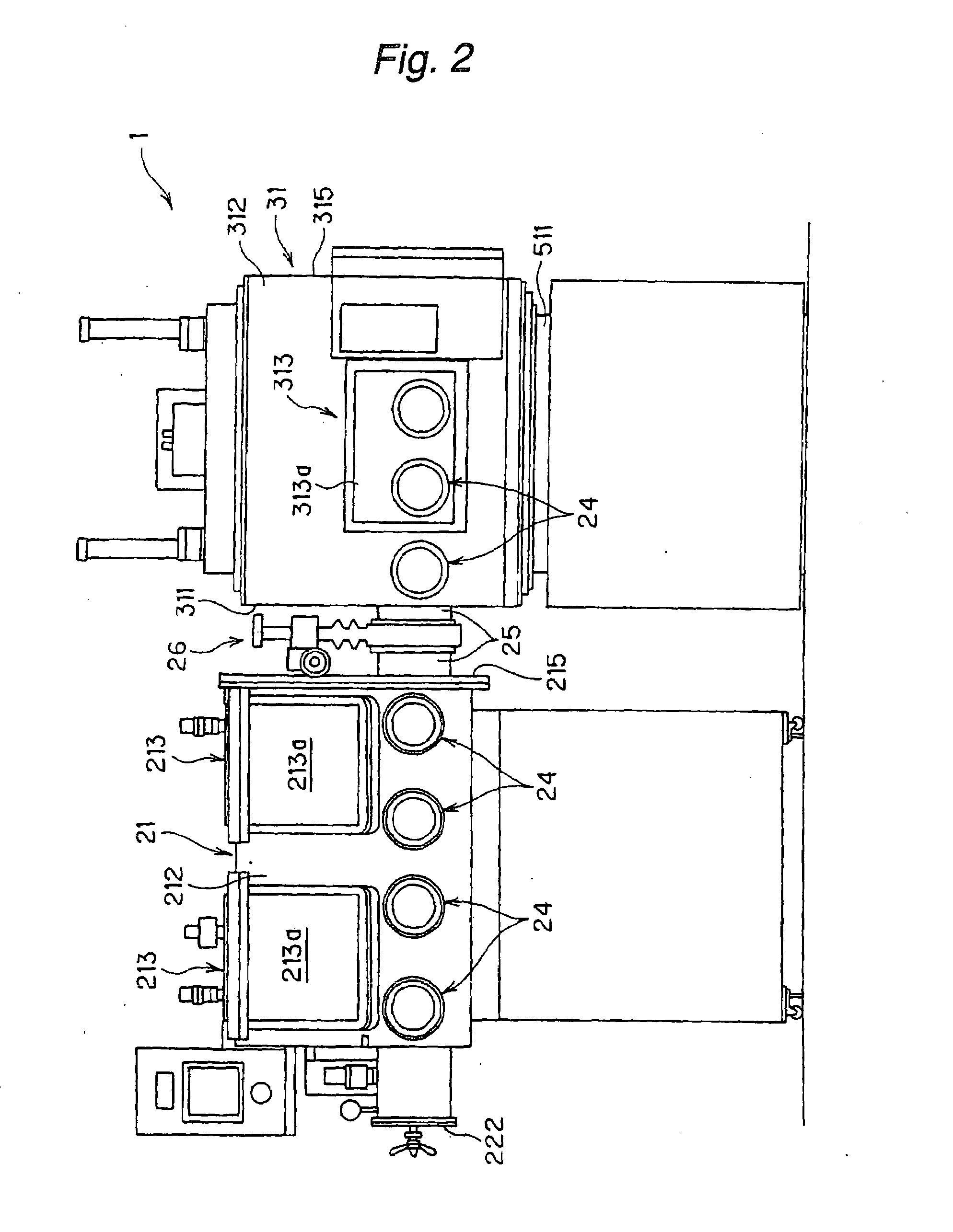
[0053]Preferred embodiments of a nano-precision (or nano-ultra-precision) sintering system according to the present invention will be described below with reference to the attached drawings.

[0054]For the purpose of maintaining the purity of a product by preventing degradation in the quality of a powder of a material due to oxidation in the powder and any impurities entering into the powder after its having been prepared or after a sealed container containing the powder having been unsealed and further by preventing degradation of the powder during the filling of the powder or the placing into a sintering machine, a nano-precision (nano-ultra-precision) sintering system according to an embodiment of the present invention is designed such that a series of following operations including: mixing and grinding of the powder of a material; storing the prepared powder of a material; measuring a weight of the powder of material; filling a mold with the powder of a material; and placing the s...


PUM

PropertyMeasurementUnit
pressureaaaaaaaaaa
pressureaaaaaaaaaa
grain structureaaaaaaaaaa

Abstract

The present invention provides a nano-precision sintering system 1 for sintering a nano-sized powder of a material in the pulse energization and pressure sintering process to obtain a highly purified sintered compact having a nano-sized grain structure, said nano-precision sintering system 1 comprising: at least one pre-process chamber 20 defined by at least one sealed housing 21 having at least one glove and designed to be controlled into a predetermined atmosphere; a sintering process chamber 30 defined by a sealed housing 31 having at least one glove and designed to be controlled into a predetermined atmosphere; a shut-off system 26 disposed in a passage providing communication between the pre-process chamber and the sintering process chamber so as to block the communication between the two chambers selectively while keeping it in an air tight condition; and a pulse energization and pressure sintering machine 50 having a vacuum chamber “C” allowing for the sintering process to be carried out under a vacuum atmosphere, wherein the vacuum chamber is disposed in the sintering process chamber such that the former can be isolated from the latter.

Description

TECHNICAL FIELD[0001]The present invention relates to a nano-precision sintering system for manufacturing a sintered compact having nano-sized grains and / or crystalline structures, and more specifically, to a nano-precision sintering system for manufacturing a sintered compact having nano-sized grains and / or crystalline structures by sintering a nano-sized powder of a starting material, while suppressing grain growth, by using a pulse energization and pressure sintering process.BACKGROUND ART[0002]Recently, studies on a nano-structural material have been conducted in various fields. Particularly in the field of powder sintering, a technology has been studied and developed that is directed to produce a sintered compact (for e.g., a nano-phase material based on metals or ceramics, a nano-composite material and the like) by using a nano-sized powder of a starting material. A sintering process typically takes a long time with a prior art sintering process that simply provides heating an...

Claims


Application Information

Patent Timeline
Patent Type & Authority Applications(United States)
IPC IPC(8): B22F3/105B29C35/08
CPCB22F3/14B22F2998/00B22F2999/00F27B9/04F27B19/04B22F1/0044B22F2201/10B22F2201/20B22F1/07B82B3/00B82Y40/00
Inventor TOKITA, MASAOSUZUKI, SHINICHINAKAGAWA, KATSUYUKI
Owner FUJI ELECTRONICS IND
Why Eureka
Try Eureka