Rack type safe brake device for electromagnetic lever of lifting equipment

A technology of lifting equipment and safety braking, which is applied in elevators, hoisting devices, transportation and packaging, etc., and can solve problems such as inability to produce braking effects

Active Publication Date: 2017-05-31
徐州市万铭精密铸造有限公司
View PDF6 Cites 7 Cited by
  • Summary
  • Abstract
  • Description
  • Claims
  • Application Information

AI Technical Summary

Problems solved by technology

[0002] The safety braking measures of the existing rack and pinion lifting equipment are either by braking the motor shaft, or by braking the gear shaft, or by braking the shaft of the intermediate transmission link. These methods actually The friction brake is used to stop the gear from rotating to achieve braking; the prerequisite is that the driving gear must maintain the braking performance. If there is a problem with the driving gear, such as gear teeth failure, stopping the gear to achieve braking will not produce braking. However, the use of rack brakes is a feasible method to ensure reliable braking regardless of whether the gears fail.

Method used


Image

  • Rack type safe brake device for electromagnetic lever of lifting equipment
  • Rack type safe brake device for electromagnetic lever of lifting equipment
  • Rack type safe brake device for electromagnetic lever of lifting equipment

Examples


Embodiment 1

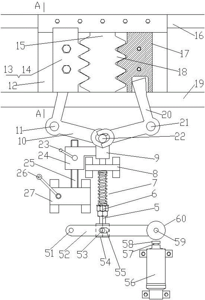
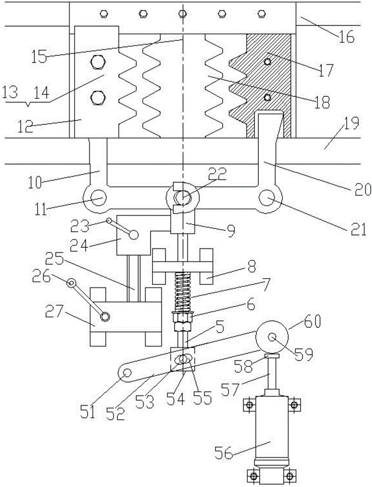
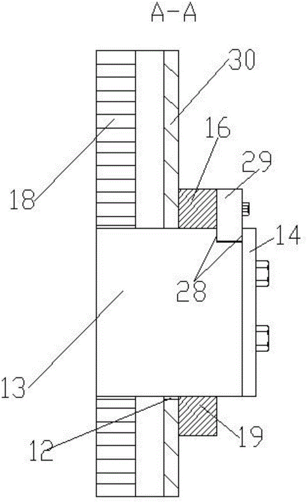
[0021] Embodiment 1, a lifting device equipped with an electromagnetic lever rack type safety brake device directly installed on the lifting device car, Figure 7 It is a schematic diagram of the appearance of Embodiment 1, which shows the appearance of the side of the elevator. The electromagnetic lever and rack type safety brake device is installed on the rack and pinion lifting equipment and is temporarily in a free position, and the lifting equipment is ready to run or is running Case, Figure 8 It is a schematic diagram of the appearance of the electromagnetic lever rack type safety braking device of embodiment 1 braking the lifting equipment, (the left and right described in the previous figure are viewed from the inside of the lifting equipment to the side of the lifting equipment, Figure 7 , 8 It is viewed from the outside to the side of the lifting equipment, so the left and right directions are just opposite), the electromagnetic lever rack type safety brake device...

Embodiment 2

[0022] Embodiment 2 is a lifting device equipped with an independent safety brake device assembly of the electromagnetic lever and rack type safety brake device of the present invention, Figure 9 It is a schematic diagram of the appearance of Embodiment 2, which shows the situation when the electromagnetic pusher main body 1 is in a power-off state, and the rack-type safety brake device is driven by electromagnetic force to perform braking. Figure 10 In embodiment 2, when the main body 1 of the electromagnetic pusher is in the energized state and the electromagnetically driven rack-type safety brake device is in a free position state, the specific structure of the electromagnetic lever rack-type safety brake device used in the lifting equipment is An independent safety brake device assembly that is separately set up as an independent assembly and then installed on the lifting equipment, Figure 11 It is a schematic diagram of an independent safety brake device assembly of th...

Embodiment 3

[0023]Embodiment 3, an elevator equipped with an electromagnetic lever rack type safety brake assembly directly installed on the car of the lifting equipment, its appearance is the same as Figure 7 , Figure 8 , the working principle is the same as that described in paragraph [0021].


PUM


Abstract

The invention provides a rack type safe brake device for an electromagnetic lever of lifting equipment. A movable rack can horizontally move or can be kept on certain designated position on a rail component; after entering a brake state, the top of the movable rack is directly contacted with the main bearing structure of a cage of the lifting equipment or is contacted with bearing through an intermediate transition bearing part; an operation mechanism of the movable rack is used for operating the movable rack to horizontally move or stay on certain designated position on the rail component; and the designated position includes a brake position meshed with a driving rack of the lifting equipment or a free position which is completely separated from the driving rack of the lifting equipment at an interval. An electromagnetic lever is adopted to control the rack meshing mode for safe protection brake, and the beneficial effects of saving energy, remarkably improving the levelling accuracy and safely protecting the brake quality can be achieved.

Description

technical field [0001] The invention relates to the field of safety braking devices for lifting equipment, in particular to an electromagnetic lever rack type safety braking device for lifting equipment. Background technique [0002] The safety braking measures of the existing rack and pinion lifting equipment are either by braking the motor shaft, or by braking the gear shaft, or by braking the shaft of the intermediate transmission link. These methods actually The friction brake is used to stop the gear from rotating to achieve braking; the prerequisite is that the driving gear must maintain the braking performance. If there is a problem with the driving gear, such as gear teeth failure, stopping the gear to achieve braking will not produce braking. The dynamic effect is achieved; and the use of rack brakes is a feasible method to ensure reliable braking regardless of whether the gears fail. Contents of the invention [0003] The purpose of the present invention is to p...

Claims


Application Information

Patent Timeline
Patent Type & Authority Applications(China)
IPC IPC(8): B66B5/26B66B1/42B66B11/04B66D5/24B66D5/30
CPCB66B1/365B66B1/42B66B5/26B66B11/0415B66D5/24B66D5/30
Inventor 廖忠民
Owner 徐州市万铭精密铸造有限公司
Why Eureka
Try Eureka