Rotary gravity type clocked trigger

A trigger and gravity technology, applied in the field of rotating gravity timing triggers, can solve problems such as effects affecting timing

Active Publication Date: 2017-05-31
济南市嬴磊信息科技有限公司
View PDF6 Cites 3 Cited by
  • Summary
  • Abstract
  • Description
  • Claims
  • Application Information

AI Technical Summary

Problems solved by technology

For the two timing technologies mentioned above, the spring timing has a service life because of the deformation of the spring, so the spring timing technology has a certain service life; as for th

Method used


Image

  • Rotary gravity type clocked trigger
  • Rotary gravity type clocked trigger
  • Rotary gravity type clocked trigger

Examples


Embodiment Construction

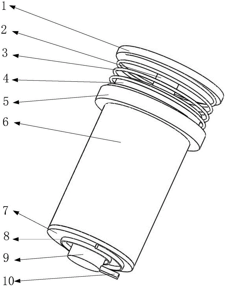
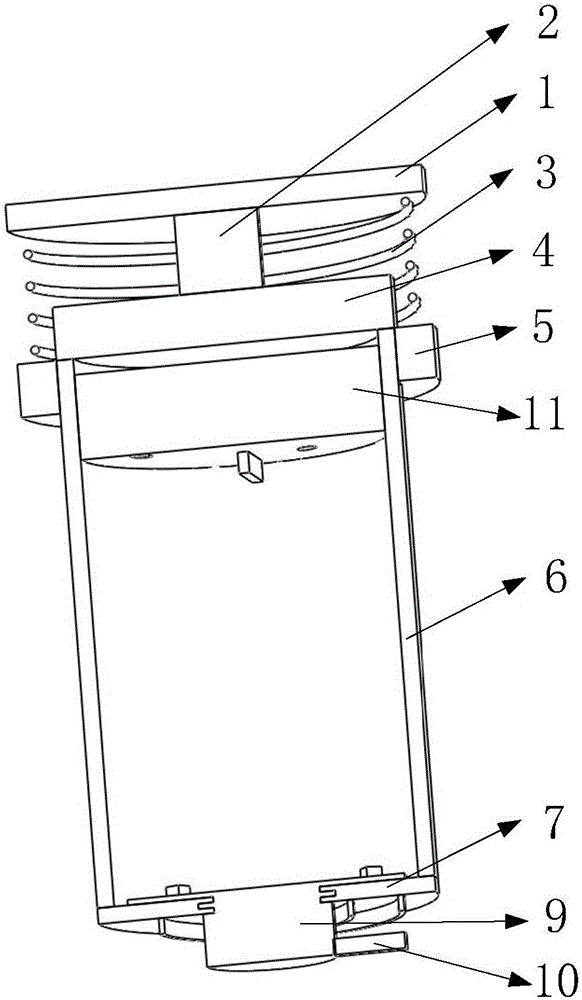
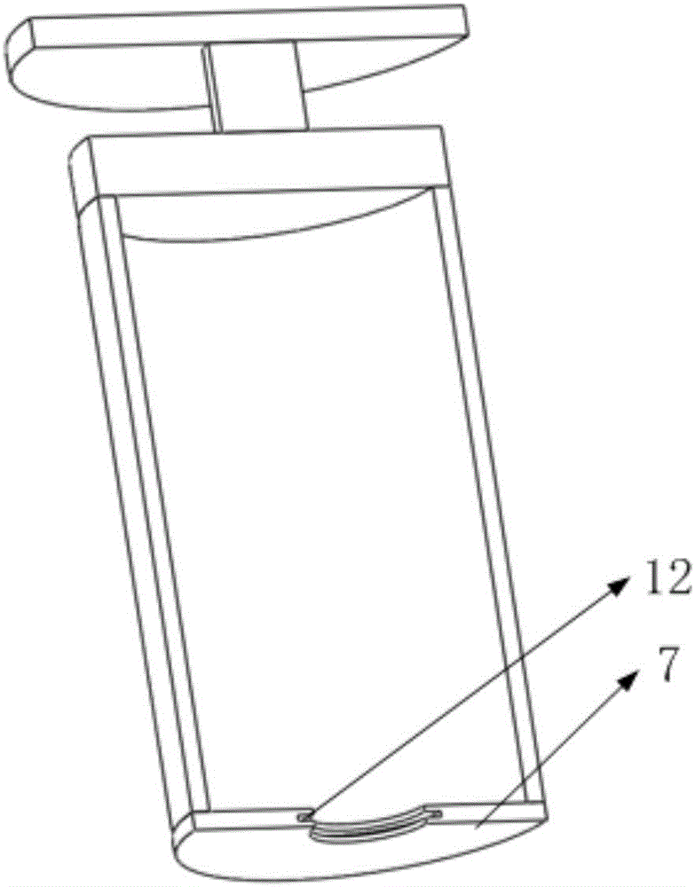
[0024] Such as figure 1 , 2 As shown, it includes support cover, pillar, vibrating spring, top cover, vibrating ring, shell, bottom plate, scroll spring, trigger post, gravity plug, bottom plate groove, among which figure 2 As shown, the top cover is installed on the upper end of the shell, and the gravity plug is installed and slides inside the shell; image 3 As shown, the support cover is installed on the upper side of the top cover through struts, such as figure 1 As shown, the vibration ring is a permanent magnet, and the vibration ring is nested on the outer surface of the housing and slides on the outer surface of the housing. One end of the vibration spring is installed on the bottom of the support cover, and the other end is installed on the upper side of the vibration ring. The side is nested on the outer edge of the top cover; the base plate is installed on the lower side of the housing, and the trigger column is installed on the base plate; the housing is filled...


PUM


Abstract

The invention belongs to the technical field of mechanical timing, and particularly relates to a rotary gravity type clocked trigger. The rotary gravity type clocked trigger comprises a shaking spring, a top cover, a shaking ring, a shell body, a bottom plate, a volute spiral spring, a triggering column and a gravity plug, wherein a fluid oil exists in the shell body, a hydraulic hole is formed in the gravity plug, and the hydraulic oil flows through the hydraulic hole of the gravity plug when the gravity plug moves from the upper part to the lower part; when the gravity plug is close to the bottom plate, a drive stirring block and a driven stirring block are contacted and collide to promote the triggering column to start rotating so as to trigger an outside mechanism. When a timer is shaken, the shaking ring is driven by the external force to swing up and down in a reciprocating manner, then the gravity plug starts to move downwards, and the timing is started. As the hydraulic oil has the effects of lubricating and isolating air from the gravity plug, the gravity plug and the shell body do not have the changes of oxidation or precision, then the timer has the effect of long service life; as no electric power takes part, the range of application is also quite extensive. The rotary gravity type clocked trigger has a better use effect.

Description

[0001] Technical field [0002] The invention belongs to the technical field of mechanical timing, in particular to a rotary gravity timing trigger. Background technique [0003] Timing technology From the traditional mechanical spring timing to the most widely used electronic timing technology, timing technology can be described as a wide variety. For the two timing technologies mentioned above, the spring timing has a service life because of the deformation of the spring, so the spring timing technology has a certain service life; as for the electronic timing technology, it is limited by power. In some special occasions, if there is no The location of electricity, or the situation of unstable electricity will affect the timing effect. Therefore, designing a timer that does not use electricity and has a long service life will have certain application prospects. [0004] The present invention designs a rotating gravity timing trigger to solve the above problems. Contents o...

Claims


Application Information

Patent Timeline
IPC IPC(8): G04F1/04
CPCG04F1/04
Inventor 冯林
Owner 济南市嬴磊信息科技有限公司
Why Eureka
Try Eureka