Reflecting surface folding and unfolding structure of foldable and deployable antenna of space-based radar

A space-based radar and reflector technology, which is applied to folded antennas, antennas, inflatable antennas, etc., can solve the problems of heavy weight, high aspect ratio and complex structure, and achieve the effect of simple structure, light weight and high storage ratio.

Active Publication Date: 2017-05-31
HARBIN INST OF TECH
View PDF4 Cites 9 Cited by
  • Summary
  • Abstract
  • Description
  • Claims
  • Application Information

AI Technical Summary

Problems solved by technology

[0002] Space-based radar can work around the clock, has large-scale, high-precision detection capabilities, and has capabilities that optical systems, ground-based radars, and airborne radars do not have; due to the many advantages of space-based radar, it has received extensive attention and research from many countries ; The large phased array planar antenna with a length of hundreds of meters and an area of ​​several hundred square meters is an important part of space-based radar. The antenna has a large area and a high aspect ratio. In order to facilitate transportation, the antenna must be folded on the ground. After being launched into space, the work is started. The existing foldable and unfoldable antennas mainly have two supporting and unfolding methods: mechanical and inflatable. The mechanical structure is complex and the weight is relatively large. Expansion and contraction are obvious, and the stability after unfolding is not ideal

Method used


Image

  • Reflecting surface folding and unfolding structure of foldable and deployable antenna of space-based radar
  • Reflecting surface folding and unfolding structure of foldable and deployable antenna of space-based radar
  • Reflecting surface folding and unfolding structure of foldable and deployable antenna of space-based radar

Examples


Embodiment Construction

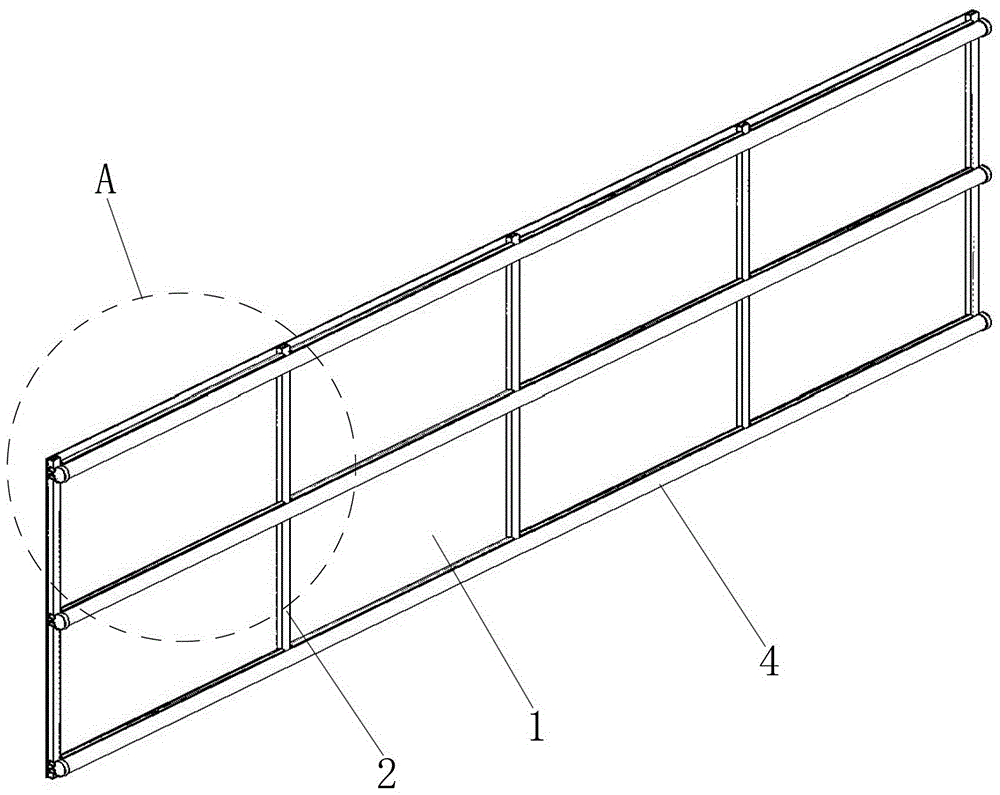
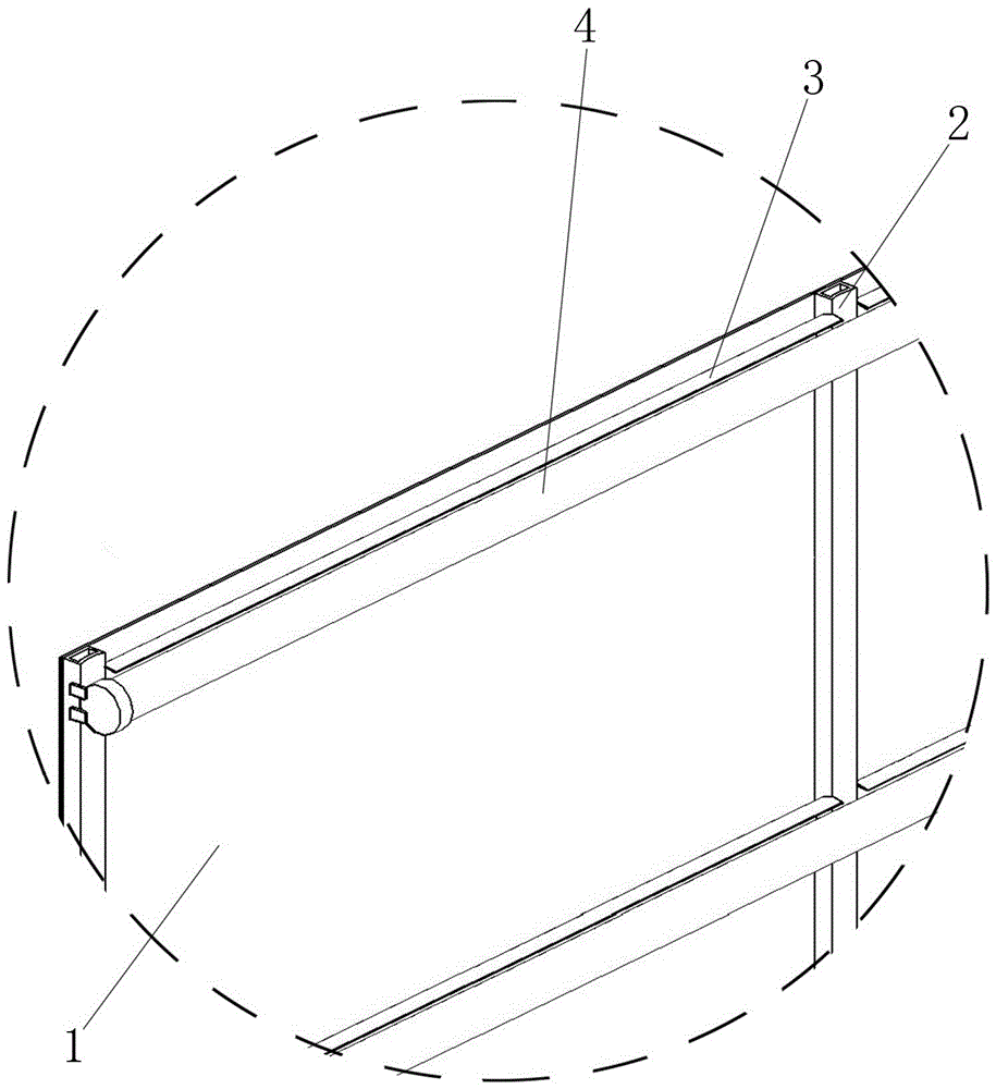
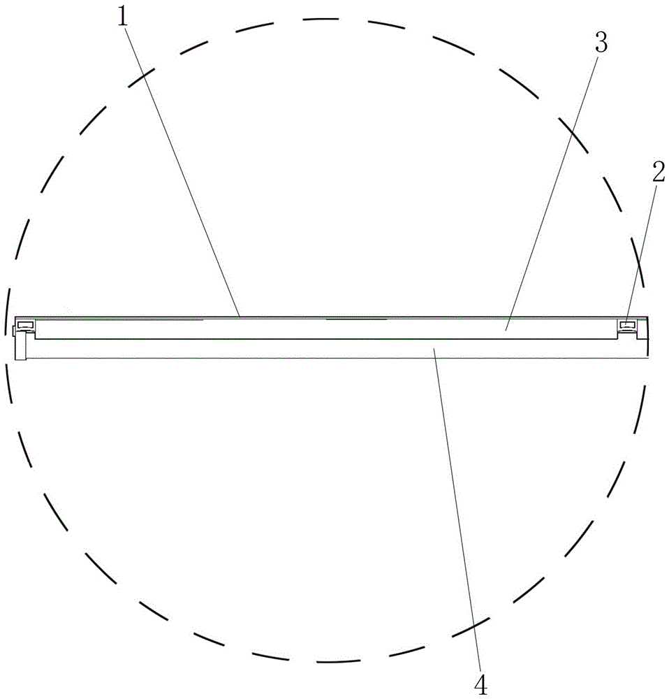
[0016] refer to Figure 1 to Figure 8 , a space-based radar foldable and unfoldable antenna reflecting surface folding structure, which includes a reflecting surface 1, a transverse rib 2, a bistable composite material foldable cylindrical shell 3 and an auxiliary deployment inflatable arm 4, and the reflecting surface 1 is rectangular , one side surface of the reflective surface 1 is provided with a plurality of transverse ribs 2 arranged along the width direction of the reflective surface 1, the transverse ribs 2 are bonded to the reflective surface 1, the transverse ribs 2 are hollow tubular structures, the transverse ribs 2 and the reflective The bonding surface of the surface 1 is a plane, and the surface opposite to the bonding surface of the transverse rib 2 and the reflective surface 1 is a concave arc surface. The arc surface can not only improve the stiffness of the transverse rib 2, but also effectively reduce the reflective surface 1 after folding. volume; at least...


PUM


Abstract

The invention provides a reflecting surface folding and unfolding structure of a foldable and deployable antenna of space-based radar, belongs to the technical field of the space-based radar and solves the problems of existing foldable and deployable antennas. The reflecting surface folding and unfolding structure comprises a reflecting surface, transverse ribs, bistable composite foldable and deployable cylindrical shells and auxiliary unfolding inflatable arms, wherein the reflecting surface is rectangular, the multiple transverse ribs arranged in the width direction of the reflecting surface are mounted on the surface of one side of the reflecting surface, are bonded with the reflecting surface and adopt a hollow tubular structure, the surface, bonded with the reflecting surface, of each transverse rib is a plane, and the surface, opposite to the surface bonded with the reflecting surface, of each transverse rib is an indent arc surface; at least two bistable composite foldable and deployable cylindrical shells are arranged between every two adjacent transverse ribs, and two ends of each bistable composite foldable and deployable cylindrical shell are contacted with the adjacent transverse ribs respectively; the two transverse ribs located on the outmost side of all the transverse ribs are connected through the at least two auxiliary unfolding inflatable arms. The reflecting surface folding and unfolding structure is applied to the space-based radar.

Description

technical field [0001] The invention belongs to the technical field of space-based radar, and in particular relates to a folding structure of a reflective surface of a foldable and unfoldable antenna of a space-based radar. Background technique [0002] Space-based radar can work around the clock, has large-scale, high-precision detection capabilities, and has capabilities that optical systems, ground-based radars, and airborne radars do not have; due to the many advantages of space-based radar, it has received extensive attention and research from many countries ; The large phased array planar antenna with a length of hundreds of meters and an area of ​​several hundred square meters is an important part of space-based radar. The antenna has a large area and a high aspect ratio. In order to facilitate transportation, the antenna must be folded on the ground. After being launched into space, the work is started. The existing foldable and unfoldable antennas mainly have two su...

Claims


Application Information

Patent Timeline
Patent Type & Authority Applications(China)
IPC IPC(8): H01Q1/08H01Q15/14
CPCH01Q1/081H01Q15/14
Inventor 谭惠丰沈永正卫剑征
Owner HARBIN INST OF TECH
Why Eureka
Try Eureka