Adjustable clamp special for milling plane

The technology of milling plane and fixture is applied in the field of special adjustable fixture for milling plane, which can solve the problems of low manufacturing precision, large roughness value, poor clamping effect, etc., and achieve the effects of convenient operation, good clamping effect and simple structure.

Inactive Publication Date: 2017-06-30
邓加滨
View PDF5 Cites 4 Cited by
  • Summary
  • Abstract
  • Description
  • Claims
  • Application Information

AI Technical Summary

Problems solved by technology

The manufacturing precision of traditional milling fixtures is low, the

Method used


Image

  • Adjustable clamp special for milling plane
  • Adjustable clamp special for milling plane
  • Adjustable clamp special for milling plane

Examples


Embodiment 1

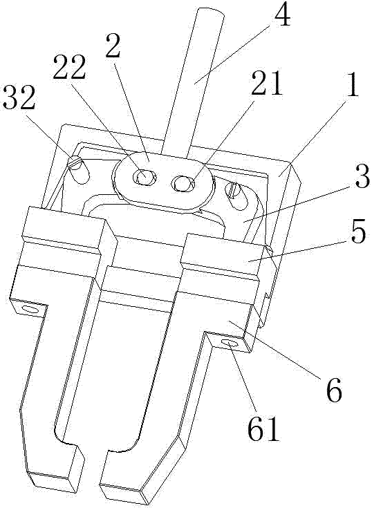
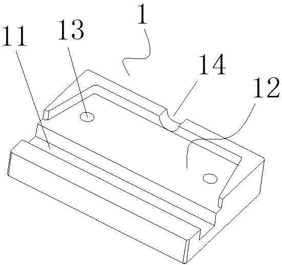
[0024] as attached figure 1 with Figure 3 ~ Figure 5 As shown, the special adjustable clamp for milling plane of the present invention provides a technical solution that includes a clamp base 1, a waist-shaped connector 2, a corner piece 3, a push handle 4, a convex slider 5, a clamping arm 6, and a bar-shaped Chute 11, trapezoidal groove 12, circular hole 13, semicircular groove 14, waist-shaped hole 21, fixing pin 22, circular corner hole 31, tightening pin 32, ball hinge 33, rotating hole 34, the first installation Holes 51 and second mounting holes 61, the upper surface of the trapezoidal groove 12 is provided with a circular hole 13 that does not penetrate the bottom surface, and two corner pieces, one left and one right, are respectively embedded in the upper surface of the trapezoidal groove 12 3. Each of the corner fittings 3 has a 90° corner structure, and a circular corner hole 31 is provided at the corner, a ball hinge 33 is provided at one end of the corner, and ...

Embodiment 2

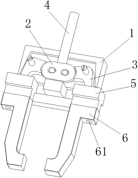
[0026] as attached Figure 2 to Figure 5 As shown, the special adjustable clamp for milling plane of the present invention provides a technical solution that includes a clamp base 1, a waist-shaped connector 2, a corner piece 3, a push handle 4, a convex slider 5, a clamping arm 6, and a bar-shaped Chute 11, trapezoidal groove 12, circular hole 13, semicircular groove 14, waist-shaped hole 21, fixing pin 22, circular corner hole 31, tightening pin 32, ball hinge 33, rotating hole 34, the first installation Holes 51 and second mounting holes 61, the upper surface of the trapezoidal groove 12 is provided with a circular hole 13 that does not penetrate the bottom surface, and two corner pieces, one left and one right, are respectively embedded in the upper surface of the trapezoidal groove 12 3. Each of the corner fittings 3 has a 90° corner structure, and a circular corner hole 31 is provided at the corner, a ball hinge 33 is provided at one end of the corner, and a rotating hol...


PUM


Abstract

The invention relates to a special adjustable clamp for milling plane, comprising a clamp base, a strip-shaped chute and a trapezoidal groove are respectively provided on the clamp base, and the upper surface of the trapezoidal groove is provided with a circular hole that does not penetrate the bottom surface Two left and right corner pieces are embedded on the upper surface of the trapezoidal groove, respectively, a waist-shaped connecting piece is installed above each corner piece, and left and right convex slides are embedded on the strip chute respectively. Each of the convex slider bosses is connected with a clamping arm respectively, and a push handle capable of rotating the left and right corner pieces is installed on the outer side of the waist-shaped connecting piece, on the front side of the upper surface of the fixture base There is also a semi-circular groove in the middle of the edge, and the shape of the semi-circular groove is a sliding tangent matching structure with the journal where the push handle extends. Well, it has the characteristics of being able to adjust, stabilize and clamp the workpiece to be processed effectively and flexibly at any time.

Description

technical field [0001] The invention relates to the technical field of metal cutting, in particular to a special adjustable clamp for milling planes. Background technique [0002] Cutting is a common metal cold working method, which refers to cutting off the excess material layer on the blank or workpiece with cutting tools (including tools, abrasives and abrasives) to form chips, so that the workpiece can obtain the specified geometry, size and surface quality processing methods. The technological characteristics of cutting processing are determined by the structure of the cutting tool and the relative motion between the cutting tool and the workpiece. According to the process characteristics, cutting processing can generally be divided into: turning, milling, drilling, grinding and ultra-precision machining. And milling is to fix the blank, and use a high-speed rotating milling cutter to move on the blank to cut out the required shape and features. The difference betwee...

Claims


Application Information

Patent Timeline
IPC IPC(8): B23Q3/06
CPCB23Q3/06
Inventor 邓加滨
Owner 邓加滨
Why Eureka
Try Eureka